
2 layers36.3 × 20.8 mm
LPF
kholia/Global-Communications-Transceiver
Open-source files for Global Communications Transceiver
14 parts6GPL-3.0

Open-source files for Global Communications Transceiver
HF PA v10 is an open-source printed circuit board by kholia, from the kholia/Global-Communications-Transceiver repository on GitHub, published under the GPL-3.0 licence. It is a 2-layer board of 90 × 99.9 mm with 102 parts on 78 nets, routed with 524 tracks and 299 vias.
It is built around the MCP6002-I/P, UCC27517ADBVR-TP and AMS1117-3.3, with the L7812, SS34 and FQD7P20TM among its other parts. Its parts include 44 capacitors, 14 resistors, 7 ICs, 7 diodes and 5 transistors. It belongs with the radio and wireless boards and the RP2040 boards of this library.


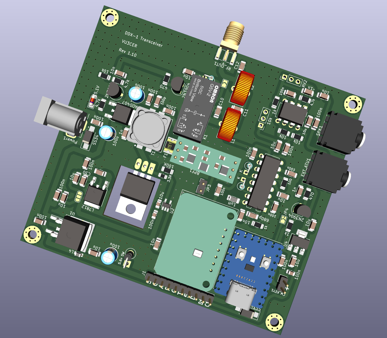
The Global Communications Transceiver project. Global-Communications-Transceiver
is a 5W radio transceiver which is rugged, simple, and reliable.
It is a optionally silent digital radio which can be heard almost all over
the world!
Note: Receiving amateur and CB radio traffic without any license is fine in most countries - please check your local regulations to be sure. Transmitting on amateur shortwave bands usually requires an amateur radio license but you are free to transmit and experiment on the CB band.
https://en.wikipedia.org/wiki/Citizens_band_radio_in_India
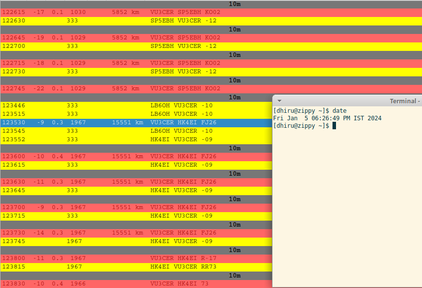
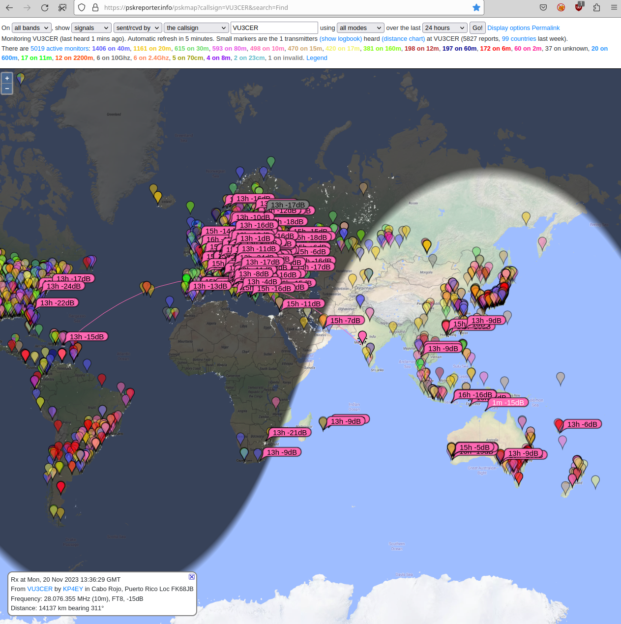
Sample contact from Pune to Medellin on 10m (15691km):
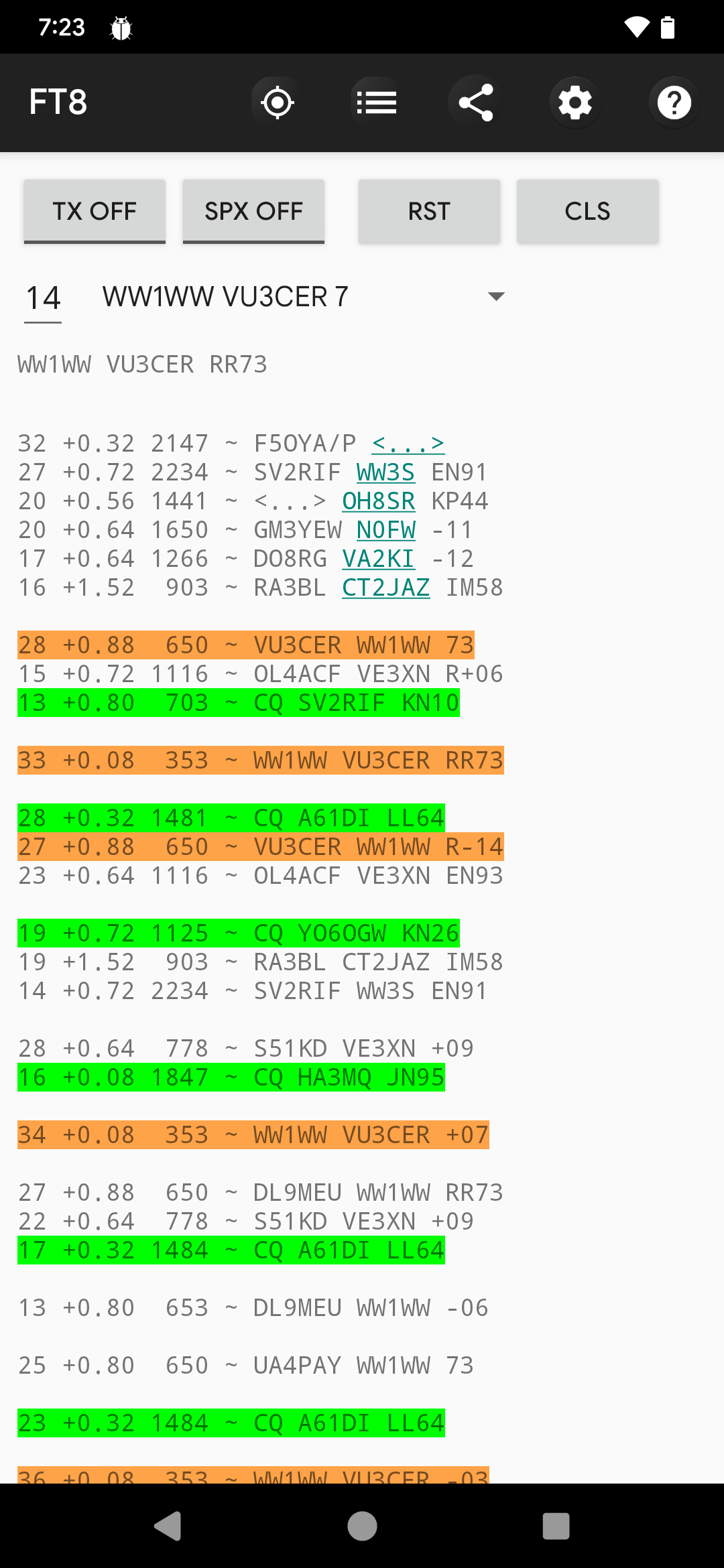
Another sample conact with WW1WW (Pune to USA):
Single USB-C cable for handling both Audio + CAT control
True 5W output on all HF bands. It even outputs ~1-2 W @ 50 MHz! (We now just need a 6m capable receiver section to build a 6m digital transceiver).
Rock-solid PA which handles open, short, and bad SWR conditions (1:10 SWR tested). We knowingly stress-test it with untuned antennas and still manage DX (not a recommended practice for sure though).
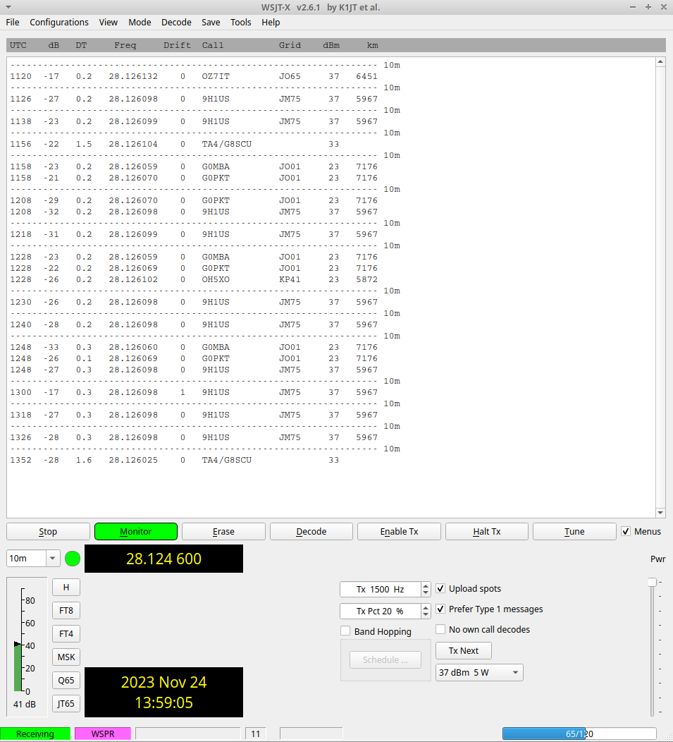
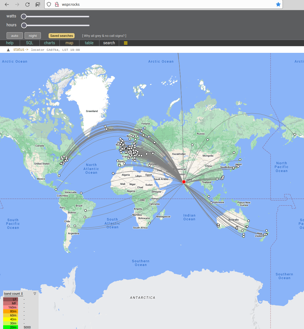
Rock-steady VFO which does NOT drift even under exposed conditions. Yes - it receives WSPR at 28 MHz just fine.
Reliable T/R switching based on a DPDT relay
Switchable BPF support to get rid of BCI and other interferences (tested against OTH radar + 100 kW AM station in close visual proximity)
No toroids to wind assuming an external LPF bank is in use ;-)
The IRF510 final remains as cool as a cucumber (Class-D operation).
Avoids problems associated with the 'audio frequency counting' approach used by earlier designs. Our transceiver has a bit-perfect, deterministic TX output.
Supports largely automated assembly from JLCPCB (all the required files are in the same GitHub repository)
It comes with a free, open-source AGPLv3 licensed firmware.
No calibration is (ever) required. Just pick it up and it is ready to go on air.
Low cost (20 to 30 USD is our BOM estimate)
Stress tested by WSJT-Z for multiple days
It routinely receives FT8 traffic from 80 to 100+ countries using a simple 5m long EFHW antenna
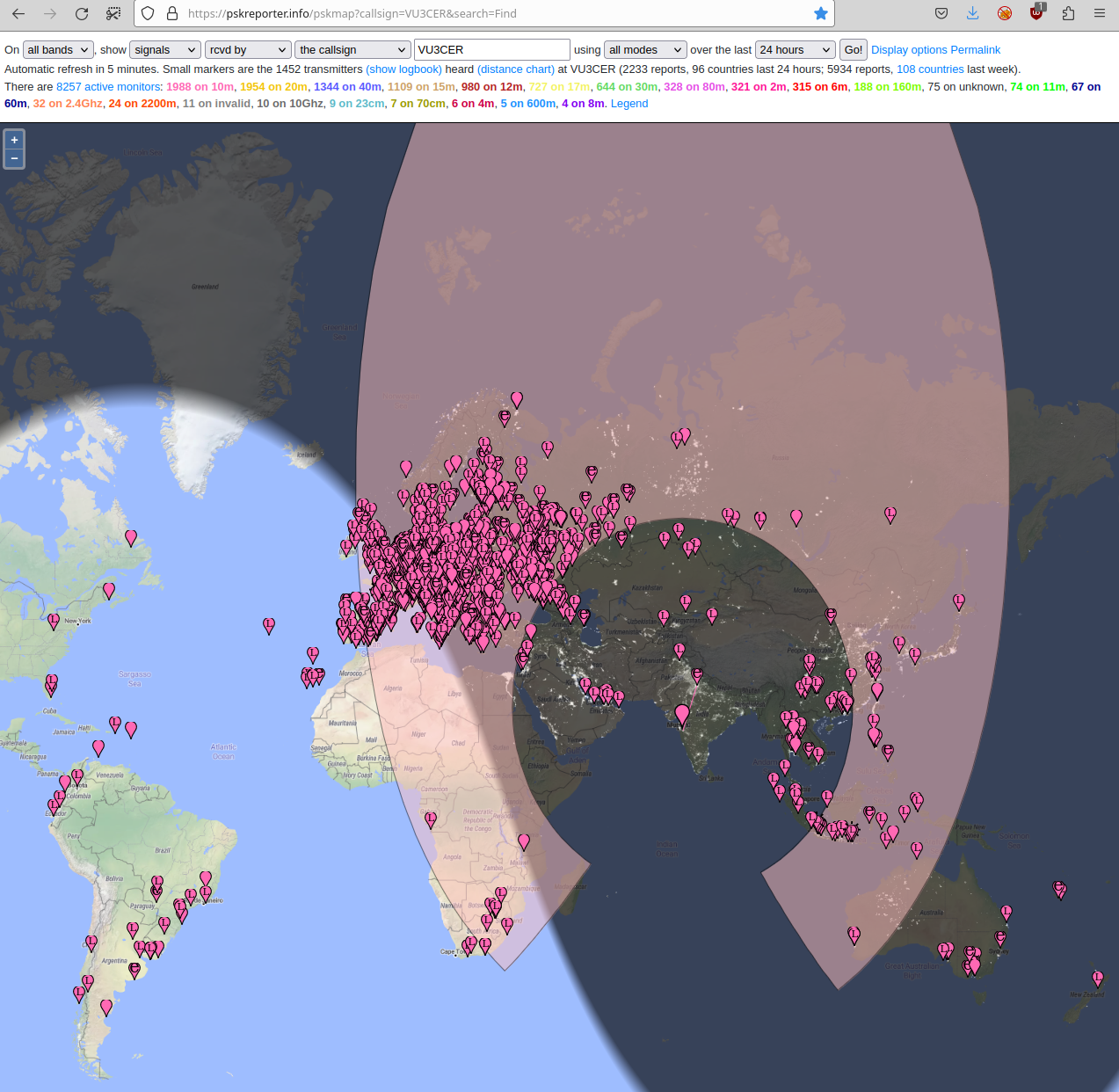
Performance of CD2003-with-BPF is >= 80% of that of RSP1 SDR, at least!
It receives WSPR @ 28 MHz ;)
With these files, you can get around 80% pre-assembled boards (with the SMD components soldered) from JLCPCB at a minimal cost.
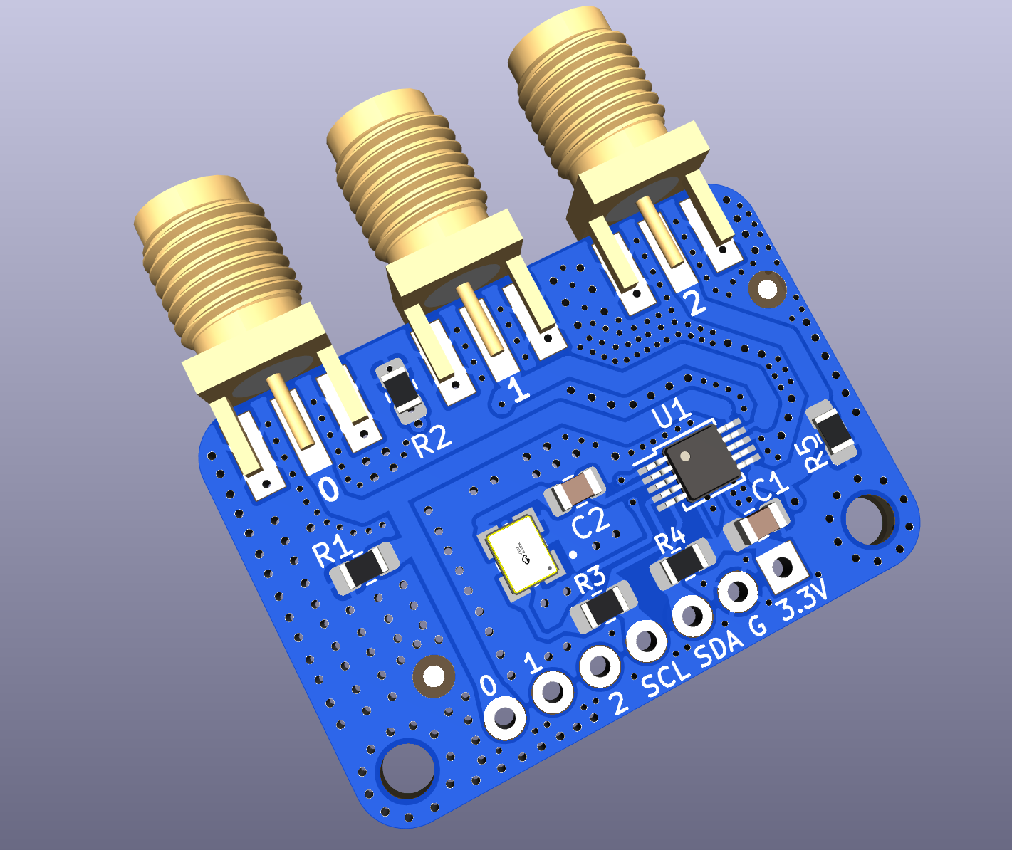
Note: The Si5351+TCXO boards can be ordered in fully assembled form from
JLCPCB. https://github.com/kholia/Si5351-Module-Clone-TCXO/ has the required
files (use the -v4 folder).
JLCPCB link: https://jlcpcb.com/
JLCPCB ordering guide: https://github.com/WB2CBA/ADX-UnO-V1.3/ has the JLCPCB ordering guide in it.
Shortcut: Upload the pre-built .uf2 file to the RP2040 Board and skip
to the next section.
Install dependencies:
sudo apt install cmake gcc-arm-none-eabi libnewlib-arm-none-eabi \
  libstdc++-arm-none-eabi-newlib git libusb-1.0-0-dev build-essential \
make g++ gccmkdir ~/repos
cd ~/reposgit clone --recursive https://github.com/kholia/tinyusb.git # use this in pico-sdk
git clone --recursive https://github.com/raspberrypi/pico-sdk.git
git clone --recursive https://github.com/kholia/Global-Communications-Transceiver.gitNow build the firmware using instructions in the firmware folder.
Load the built .uf2 file into the MCU board. Process: Hold the BOOT button on
RP2040-Zero, and then connect it to a computer. Release the BOOT button. A new
drive will open on the computer. Just drag the .uf2 firmware file (included in
the repository) to this new drive. Done!
The transceiver was tested with the following power sources.
SUGON 3005D Adjustable Digital DC Power - RECOMMENDED
3S "12V" Li-ion 18650 battery pack (RECOMMENDED for field operations)
RUIDENG DPS5020 power supply module (@13v) powered by MEAN WELL / Mornsun SMPS
Do NOT use the internal LPF + BPF filters. Just use https://github.com/kholia/DDX/tree/master/RX-TX-BPF-2025-v2 externally.
IRF510 needs to be insulated from the heat sink.
You can ignore the External ATU jack stuff.
Use a Common-Mode-Choke (attached between the rig, and the antenna) for
safety against return/back RF.
DDX works seamlessly with https://play.google.com/store/apps/details?id=com.bunzee.ft8radio app!
The Global Communications Transceiver project comes from our DDX family of
transceiver designs - https://github.com/kholia/DDX/
https://github.com/WB2CBA/ADX (the design that started it all)
http://www.learningaboutelectronics.com/Articles/Low-pass-filter-calculator.php
https://github.com/kholia/ConsensusBasedTimeSync (receiver comes from here)
https://github.com/kholia/Si5351-Module-Clone-TCXO/ (VFO comes from here)
https://github.com/kholia/HF-PA-v10 (PA comes from here)
Ruggedness philosophy: https://www.youtube.com/watch?v=4r7wHMg5Yjg
https://www.kk5jy.net/three-wire-gp/ (recommended antenna - superb for DX)
https://github.com/kholia/HF-Balcony-Antenna-System (another portable antenna setup)
https://github.com/batica81/microphone-library-for-pico (Vojislav's work makes DDX-1 possible)
| Qty | Value | Footprint | References |
|---|---|---|---|
| 16 | 100n | Capacitor_SMD:C_1206_3216Metric_Pad1.33x1.80mm_HandSolder | C1, C6, C7, C9, C14, C18, C25, C26, C27, C28, C29, C30, C32, C37, C39, C41 |
| 9 | 10u | Capacitor_SMD:C_1206_3216Metric_Pad1.33x1.80mm_HandSolder | C2, C8, C13, C24, C38, C42, C43, C45, C46 |
| 4 | MountingHole_Pad | MountingHole:MountingHole_3.2mm_M3_Pad_Via | H1, H2, H3, H4 |
| 3 | 100n | Capacitor_SMD:C_0805_2012Metric_Pad1.18x1.45mm_HandSolder | C21, C23, C47 |
| 3 | 100u | Capacitor_THT:CP_Radial_D5.0mm_P2.50mm | C5, C15, C44 |
| 3 | 10k | Resistor_SMD:R_1206_3216Metric_Pad1.30x1.75mm_HandSolder | R2, R10, R11 |
| 3 | 10n | Capacitor_SMD:C_1206_3216Metric_Pad1.33x1.80mm_HandSolder | C4, C19, C35 |
| 3 | 1N4148 | Diode_THT:D_DO-35_SOD27_P2.54mm_Vertical_KathodeUp | D3, D8, D9 |
| 3 | 1k | Resistor_SMD:R_1206_3216Metric_Pad1.30x1.75mm_HandSolder | R7, Rb1, Rin1 |
| 3 | 2N3904 | Package_TO_SOT_THT:TO-92_HandSolder | Q1, Q4, Q5 |
| 3 | 4.7k | Resistor_SMD:R_1206_3216Metric_Pad1.30x1.75mm_HandSolder | R8, R9, Rf1 |
| 2 | 120p | Capacitor_SMD:C_1206_3216Metric_Pad1.33x1.80mm_HandSolder | C10, C12 |
| 2 | 1n | Capacitor_SMD:C_1206_3216Metric_Pad1.33x1.80mm_HandSolder | C17, C20 |
| 2 | 360n | Inductor_THT:L_Toroid_Vertical_L10.0mm_W5.0mm_P5.08mm | L1, L2 |
| 2 | 470 | Resistor_SMD:R_1206_3216Metric_Pad1.30x1.75mm_HandSolder | R4, Rl1 |
| 2 | Jumper_2_Open | Jumper:SolderJumper-2_P1.3mm_Open_TrianglePad1.0x1.5mm | JP1, JP4 |
| 2 | SS34 | Diode_SMD:D_SMA_Handsoldering | D1, D2 |
| 1 | 10u | Capacitor_SMD:C_1206_3216Metric_Pad1.33x1.80mm_HandSolder | C36 |
| 1 | 100 | Resistor_SMD:R_1206_3216Metric_Pad1.30x1.75mm_HandSolder | R6 |
| 1 | 100K | Resistor_SMD:R_1206_3216Metric_Pad1.30x1.75mm_HandSolder | R1 |
| 1 | 100p | Capacitor_SMD:C_1206_3216Metric_Pad1.33x1.80mm_HandSolder | C3 |
| 1 | 10k | Connector_PinHeader_2.54mm:PinHeader_1x03_P2.54mm_Vertical | RV1 |
| 1 | 10u | Capacitor_SMD:C_0805_2012Metric_Pad1.18x1.45mm_HandSolder | C16 |
| 1 | 1uH | Inductor_SMD:L_1206_3216Metric_Pad1.22x1.90mm_HandSolder | L5 |
| 1 | 200p | Capacitor_SMD:C_1206_3216Metric_Pad1.33x1.80mm_HandSolder | C11 |
| 1 | 20k | Connector_PinHeader_2.54mm:PinHeader_1x03_P2.54mm_Vertical | RV2 |
| 1 | 2A | Fuse:Fuse_1812_4532Metric_Pad1.30x3.40mm_HandSolder | F1 |
| 1 | 3.3R | Resistor_SMD:R_0805_2012Metric_Pad1.20x1.40mm_HandSolder | R12 |
| 1 | 5.1V | Diode_SMD:D_MiniMELF | D4 |
| 1 | 5.6v 5W | Diode_THT:D_DO-15_P3.81mm_Vertical_KathodeUp | D5 |
| 1 | 680p | Capacitor_SMD:C_1206_3216Metric_Pad1.33x1.80mm_HandSolder | C31 |
| 1 | AMS1117-3.3 | Package_TO_SOT_SMD:SOT-223-3_TabPin2 | U4 |
| 1 | Bifilar XFMR | footprints:IND_SRF1260A-4R7Y-Longer-Pads | T1 |
| 1 | CD2003GB_GP | Package_DIP:DIP-16_W7.62mm | U7 |
| 1 | Conn_01x02 | Connector_PinHeader_2.54mm:PinHeader_1x02_P2.54mm_Vertical | CW_KEY1 |
| 1 | Conn_01x06 | Connector_PinHeader_2.54mm:PinHeader_1x10_P2.54mm_Vertical | J1 |
| 1 | DC-005 (Barrel Jack) | footprints:XKB_DC-005-5A-2.0_Modded | Power1 |
| 1 | EXT_ATU | footprints:PJ-307_Modded | EXT_ATU1 |
| 1 | FQD7P20 | Package_TO_SOT_SMD:TO-252-2 | Q3 |
| 1 | Ferrite Bead (2A) | Inductor_SMD:L_0805_2012Metric_Pad1.05x1.20mm_HandSolder | L4 |
| 1 | IRF510 | Package_TO_SOT_THT:TO-220-3_Horizontal_TabDown | Q2 |
| 1 | Jumper_2_Open | Connector_PinHeader_2.54mm:PinHeader_1x02_P2.54mm_Vertical | JP3 |
| 1 | L7805 (D2PAK) | Package_TO_SOT_SMD:TO-263-2 | U1 |
| 1 | L7812 | Package_TO_SOT_SMD:TO-252-2 | U3 |
| 1 | MCP6002 | Package_DIP:DIP-8_W7.62mm | U8 |
| 1 | Omron G5V-2 / OEN 46-05-2C | Relay_THT:Relay_DPDT_Omron_G5V-2 | K1 |
| 1 | Pluggable BPF | footprints:Pluggable-BPF | BPF1 |
| 1 | Power_Switch | Jumper:SolderJumper-3_P1.3mm_Open_RoundedPad1.0x1.5mm_NumberLabels | JP2 |
| 1 | RP2040-Zero | footprints:RP2040-Zero | RZ1 |
| 1 | SI5351_Module | footprints:SI5351 Module | U5 |
| 1 | SMA | Connector_Coaxial:SMA_Samtec_SMA-J-P-X-ST-EM1_EdgeMount | RF_OUT1 |
| 1 | SPEAKER | footprints:PJ-307_Modded | SPK1 |
| 1 | UCC27517ADBVR | Package_TO_SOT_SMD:SOT-23-5_HandSoldering | U2 |
| 1 | ~1n | Capacitor_SMD:C_1206_3216Metric_Pad1.33x1.80mm_HandSolder | C40 |
kholia/Global-Communications-Transceiver
Open-source files for Global Communications Transceiver

lunhuisheng/40W-CCM-Boost-PFC
40 W CCM Boost PFC 自主设计:Simulink 行为级仿真、KiCad 原理图与 RevB PCB;尚未进行实物验证。


kazushinjo/Serrasoid_TRX_29M
29MHz FM 10W transceiver with Serrasoid modulation

kholia/HF-PA-v10
HF-PA-v10 ;) Is this the end of the search for a 5W Digital PA? HF-PA-v10 is now a rugged 10W PA! We also do 100W+ now ;)


ideocentric/caryatid
Common power and I/O board for Daisy Seed instruments. One PCB layout, populated per build.

timex-sinclair-projects/tspico-hardware
Status 2026-10-19: prototype 3 (v3.0-proto3, changes below). Proto1 (v3.0-proto1) was built and brought up; proto2 added its fixes (below).
It measures 90 × 99.9 mm and has 2 copper layers, 1.6 mm thick.
102 parts, built around the MCP6002-I/P, UCC27517ADBVR-TP, AMS1117-3.3 and L7812. The full list of its parts is on this page, with links to each part's symbol and footprint where PCBKit's library has them.
From the kholia/Global-Communications-Transceiver repository on GitHub, at the commit this page was made from: the board is design-files/HF-PA-v10.kicad_pcb and its schematic 5-Pole-LPF/LPF.kicad_sch. PCBKit opens the board in the browser, with nothing to install.
Its repository publishes it under the GPL-3.0 licence: you may reuse it on that licence's terms (keep the author's notice, and for a copyleft licence share your changes alike).