2 layers99.1 × 99.7 mm
RC6502 General Video Adapter
tebl/RC6502-Apple-1-Replica
An expandable SBC-version of the Apple 1 computer, easy to get started with and lot of cool stuff that can be added to it!
80 parts193GPL-3.0

 KHit6/temperator
Smart connected device to measure 8 temperatures and 2 AC currents
Temperator is an open-source printed circuit board by KHit6, from the KHit6/temperator repository on GitHub, published under the CERN-OHL-W-2.0 licence. It is a 2-layer board of 100 × 140 mm with 86 parts on 58 nets, routed with 384 tracks and 13 vias.
It is built around the MCP6004-E/P and BAT42. Its parts include 35 resistors, 21 diodes, 13 capacitors, 5 connectors and 1 IC. It belongs with the home automation and IoT boards and the ESP32 and AVR (ATmega, ATtiny) boards of this library.


temperator is a robust and easy-to-use measurement system for taking 8 temperatures and 2 AC currents. Its design is simple yet professional. No special knowledge is required for operation. In addition to the hardware, a configuration for operation with ESPHome is provided in a separate repository. This makes integration with Home Assistant or other home automation systems very easy. Besides legacy Home Assistant connectivity, MQTT as interface protocol is also supported.
Each measurement channel is handled individually. This avoids the very common incompatibilities and difficulties in use when connecting multiple OneWire sensors together. E.g. it takes less than one minute to exchange a sensor - no more struggling with DS18B20's unique ids. Sensors with a cable length of more than 10 meters can be used without any problems. To adjust to the CT's type you can set a separate gain for each current transformer.
Particular emphasis was placed on ease of use and robust operation and favorable overall costs. A 2-layer board was sufficient for the PCB.
Further design goals of this project included:
As micro-controller an Arduino Nano ESP32 is used. This, or compatible models, offer sufficient resources to program even more complex control systems. It also allows the use of MicroPython, alternatively. Maybe, but that was no design goal, other Arduino Nanos can be used as well.
Here are some impressions of a fully assembled temperator:
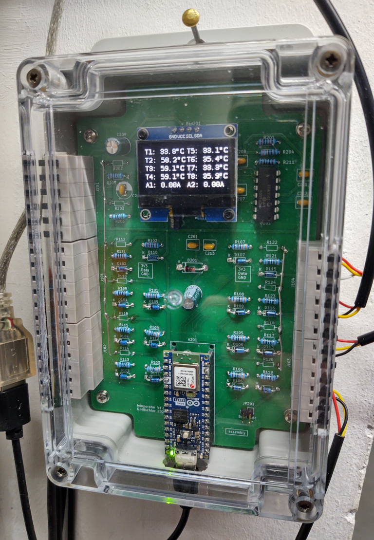
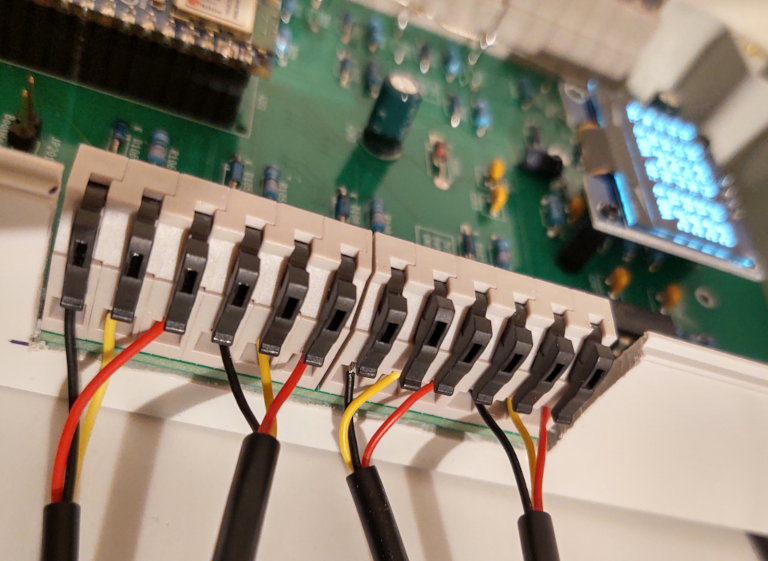
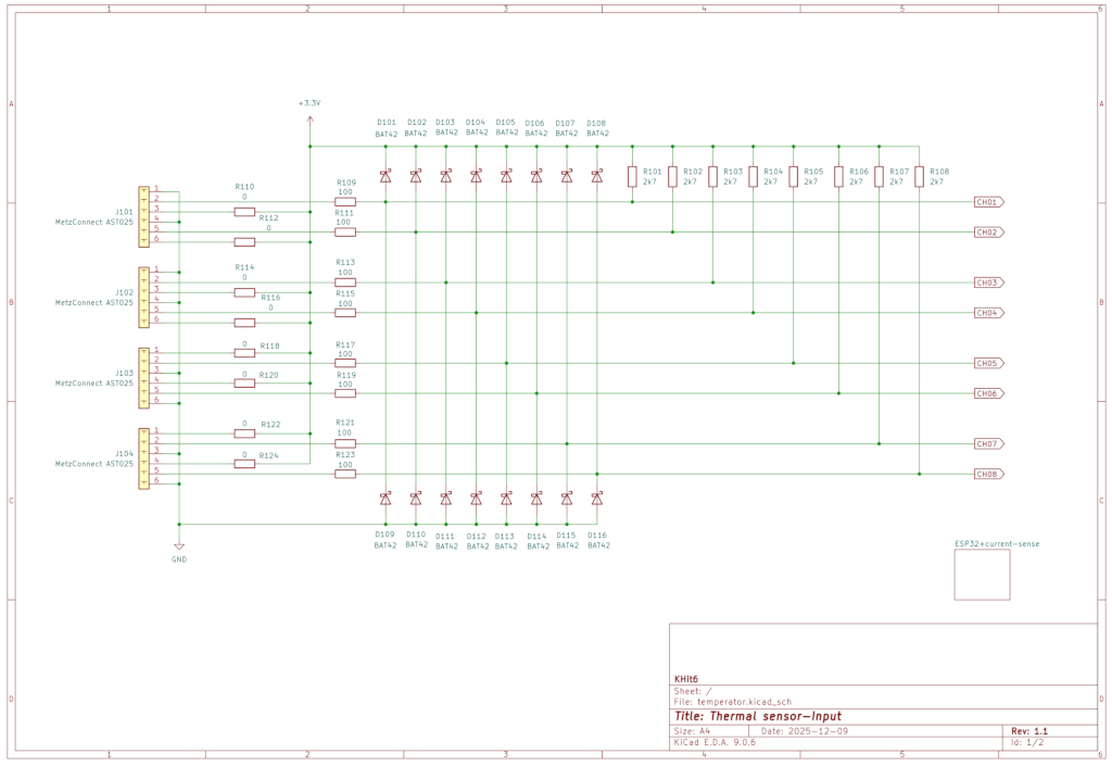
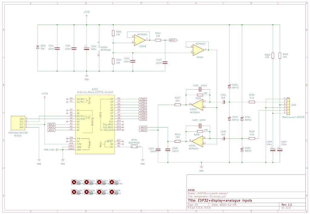
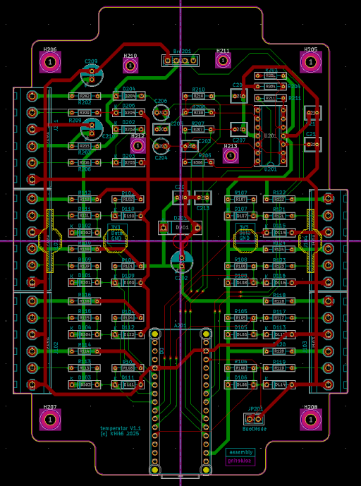
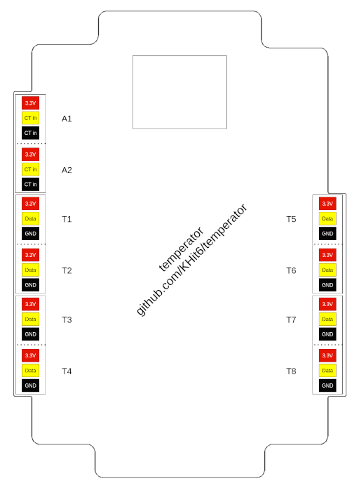
As EDA system KiCAD 9.06 was used (Great EDA tool).
temperator is subject to the "CERN OHL V2 Weakly License".
| Qty | Value | Footprint | References |
|---|---|---|---|
| 20 | BAT42 | Diode_THT:D_DO-35_SOD27_P7.62mm_Horizontal | D101, D102, D103, D104, D105, D106, D107, D108, D109, D110, D111, D112, D113, D114, D115, D116 +4 |
| 13 | 100 | Resistor_THT:R_Axial_DIN0204_L3.6mm_D1.6mm_P7.62mm_Horizontal | R109, R111, R113, R115, R117, R119, R121, R123, R202, R203, R207, R210, R211 |
| 8 | 0 | Resistor_THT:R_Axial_DIN0204_L3.6mm_D1.6mm_P7.62mm_Horizontal | R110, R112, R114, R116, R118, R120, R122, R124 |
| 8 | 2k7 | Resistor_THT:R_Axial_DIN0204_L3.6mm_D1.6mm_P7.62mm_Horizontal | R101, R102, R103, R104, R105, R106, R107, R108 |
| 6 | 100nF | Capacitor_THT:C_Rect_L4.6mm_W3.8mm_P2.50mm_MKS02_FKP02 | C201, C207, C208, C211, C212, C213 |
| 5 | MetzConnect AST025 | Terminals:TerminalBlock_MetzConnect_AST025_1x06_P5.00mm_Horizontal | J101, J102, J103, J104, J201 |
| 4 | Board | MountingHole:MountingHole_3.2mm_M3_DIN965_Pad_TopBottom | H205, H206, H207, H208 |
| 4 | Display | MountingHole:MountingHole_2.2mm_M2_DIN965_Pad_TopBottom | H210, H211, H212, H213 |
| 3 | 100u | Capacitor_THT:CP_Radial_D6.3mm_P2.50mm | C202, C209, C210 |
| 2 | 100nF | Capacitor_THT:C_Rect_L4.6mm_W3.0mm_P2.50mm_MKS02_FKP02 | C203, C205 |
| 2 | 18k | Resistor_THT:R_Axial_DIN0204_L3.6mm_D1.6mm_P7.62mm_Horizontal | R205, R208 |
| 2 | 3u3 | Capacitor_THT:CP_Radial_Tantal_D4.5mm_P2.50mm | C204, C206 |
| 2 | 5.1k | Resistor_THT:R_Axial_DIN0204_L3.6mm_D1.6mm_P7.62mm_Horizontal | R206, R209 |
| 1 | 10k | Resistor_THT:R_Axial_DIN0204_L3.6mm_D1.6mm_P7.62mm_Horizontal | R201 |
| 1 | 1k8 | Resistor_THT:R_Axial_DIN0204_L3.6mm_D1.6mm_P7.62mm_Horizontal | R204 |
| 1 | 3V6 | Diode_THT:D_DO-15_P10.16mm_Horizontal | D201 |
| 1 | Arduino_Nano_ESP32_Socket | arduino-library:Arduino_Nano_ESP32_Socket | A201 |
| 1 | BOOTMODE | Connector_PinHeader_2.54mm:PinHeader_1x02_P2.54mm_Vertical | JP201 |
| 1 | MCP6004 | Package_DIP:DIP-14_W7.62mm | U201 |
| 1 | SSD1306/SH1106 | Connector_PinHeader_2.54mm:PinHeader_1x04_P2.54mm_Vertical | Brd201 |
It measures 100 × 140 mm and has 2 copper layers, 1.6 mm thick.
86 parts, built around the MCP6004-E/P and BAT42. The full list of its parts is on this page, with links to each part's symbol and footprint where PCBKit's library has them.
From the KHit6/temperator repository on GitHub, at the commit this page was made from: the board is temperator.kicad_pcb and its schematic temperator-01.kicad_sch. PCBKit opens the board in the browser, with nothing to install.
Its repository publishes it under the CERN-OHL-W-2.0 licence: you may reuse it on that licence's terms (keep the author's notice, and for a copyleft licence share your changes alike).
tebl/RC6502-Apple-1-Replica
An expandable SBC-version of the Apple 1 computer, easy to get started with and lot of cool stuff that can be added to it!


VlastimilWagner/CherryZXKeyboard
Keyboard for ZX Spectrum based on 48p-KDLX scheme, but used Cherry MX and atypical formfactor


