2 layers41 × 41 mm
RW 5V W3 LED V5
khartinger/RCC5V
Controlling model railroad components with DCC, MQTT and manually
41 parts

 khartinger/RCC5V
Controlling model railroad components with DCC, MQTT and manually
Dcc track UI detection V2 is an open-source printed circuit board by khartinger, from the khartinger/RCC5V repository on GitHub. It is a 2-layer board of 99.1 × 33 mm with 49 parts on 30 nets, routed with 226 tracks and 1 via.
It is built around the LM393, SFH615A-3 and BC337, with the SB240, BAT48 and JUMPER2 among its other parts. Its parts include 18 resistors, 8 capacitors, 6 diodes, 4 connectors and 3 ICs. It belongs with the home automation and IoT boards of this library.


 |
Last modified: 2025-11-21 [blocked]Controlling model railroad components with DCC, MQTT and manually==> Deutsche Version |
Directly to the table of contents of this repository
Switching points is an important part of model railroading. There are many ways to control turnouts, uncouplers, disconnectable tracks and other components. Who doesn't want to be able to do this in different ways?
The following image shows a part of an RCC control (RCC = Railway-Component-Control) with information display, switching and LED feedback.
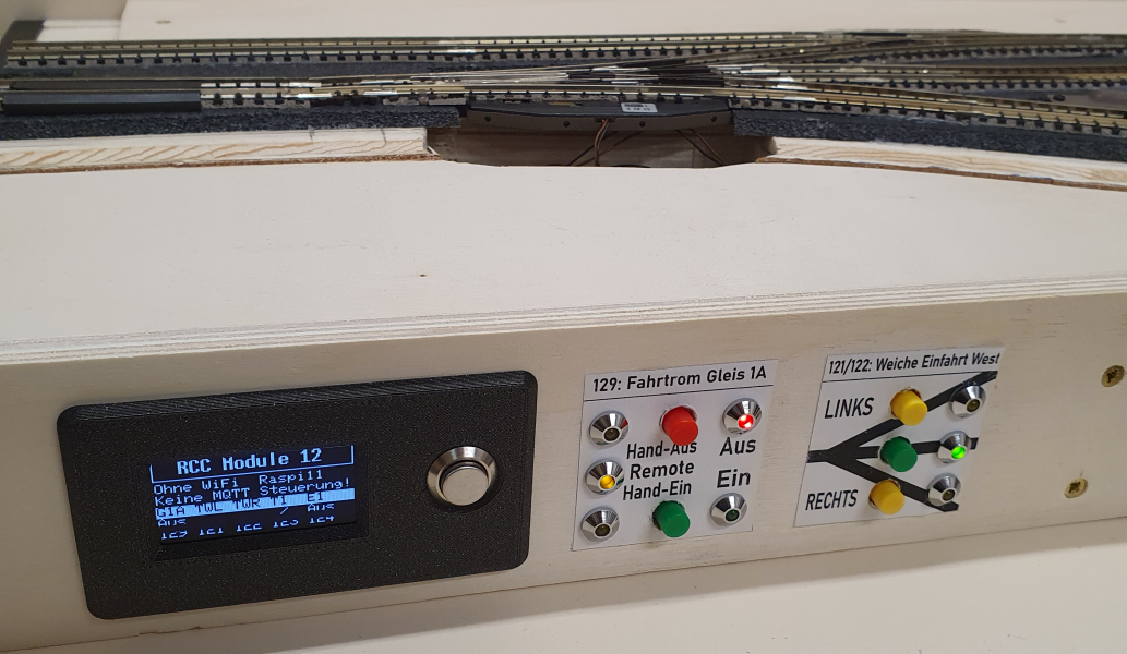
Figure 1: Example user interface RCC control unit
The simplest method of switching is, of course, to do it all by hand. In this case, you don't even need point machines. But with more distant or distributed components, this mode of operation quickly becomes cumbersome.
For this reason, magnetic drives are usually used to switch the components. In the simplest case, the AC voltage is switched directly:
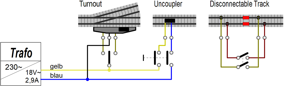
Figure 2: Direct switching of model railway components
(turnout = turnout, uncoupler = uncoupler track, disconnectable track = disconnectable track)
However, direct switching of the AC voltage has disadvantages: There is no feedback on the actual switching status and automatic switching of several components is not possible.
These disadvantages can be eliminated by commercial, digital control systems. Unfortunately, this is usually associated with considerable costs. For this reason, self-construction is an option, which also offers additional possibilities and flexibility.
If you like building things yourself, you've come to the right place. The low-cost RCC (Railway Component Control) model railroad component controller presented here allows you to switch model railroad components in three different ways:
In the standard version, up to 32 digital outputs and inputs are available. This means that a maximum of 16 two-way switches or 10 three-way switches etc. can be controlled. This number is normally sufficient for modules.
Expansion of the system is generally possible and only depends on the I²C-IO expanders used.
Some skills are advantageous for the successful use of the RCC system:
/software/rcc_demo1 /CUSTOMIZE_E.md.The detailed description of the construction of module #12: “passing loop and siding” can also be a great help.
To the top of the page
[blocked]
This repository deals with the production and use of components for controlling turnouts, uncouplers, disconnectable tracks etc. on an electric model railroad using DCC, MQTT or manually.
The following topics are covered in various subdirectories:
Information about the system
Manufacturing the system components
Software for the ESP32
Examples, use of the system
Other practical ideas for modules and the like
To the top of the page
[blocked]
The RCC system has a modular structure and mechanically consists of a series of modules or blocks. Logically, it consists of six parts:
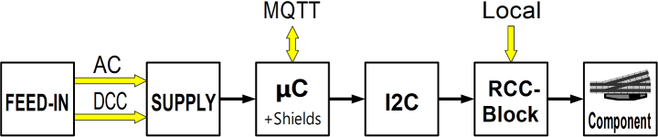
Figure 3: Block diagram for switching railroad components with 5V
By using the I2C-I/O-Expander-Boards it is possible to control several components:
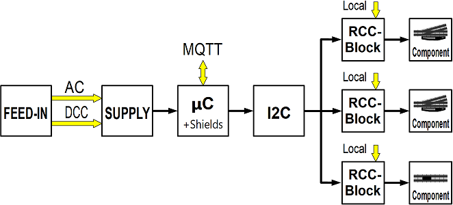
Figure 4: Block diagram switching several railroad components with 5V
Before e.g. the first switching of a turnout with RCC, some components must first be manufactured. How to do this is described in the chapter “How do I start the RCC project?” (/fab/rcc0_start/README.md).
The following figure shows an example of the modules required to control a three-way turnout:
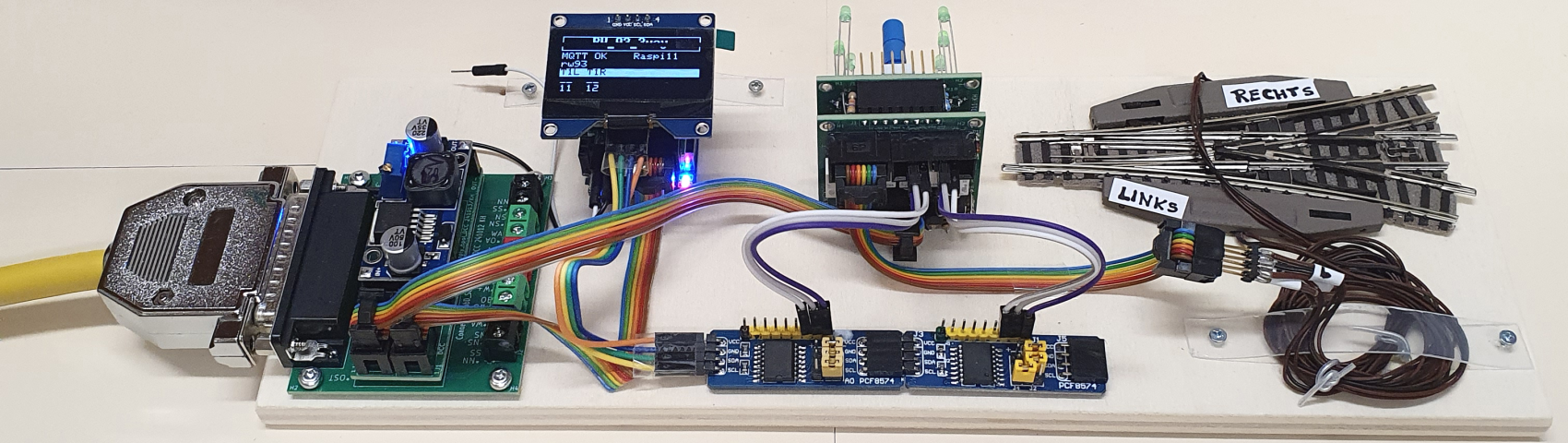
Figure 5: Demo setup of an RCC-5V system: the individual parts
On the far left you can see the 25-pin connector with the 5V power supply (“SUPPLY”), behind it is the ESP32 with a 1.56 inch display (“µC”). Two I2C-PCF8574 boards (“I2C”) are mounted in the front center, behind them the RCC block. On the right you can see a three-way turnout with two Fleischmann 640000 turnout drives. The electrical connection of the modules is made using 6-pin ribbon cables and wires.
The following image shows an example of a possible front view of a module:
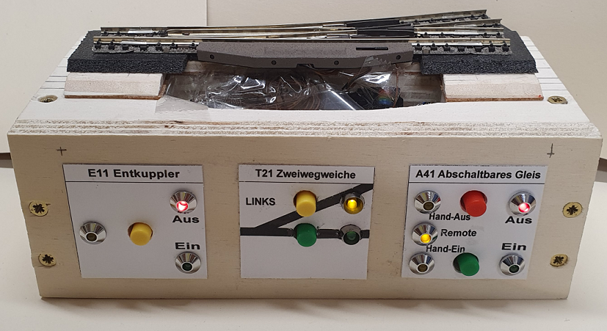
Figure 6: Example of module front view (= operating side)
To the top of the page [blocked]
The following picture shows the electrical circuit diagram for controlling a turnout with DCC, MQTT or manually. The light green rectangles represent circuit boards developed in KiCad 8.0 and manufactured by PCB Way. To do this, simply install the PCB Way plug-in in KiCad and the data required for production is then transferred with a click of the mouse.
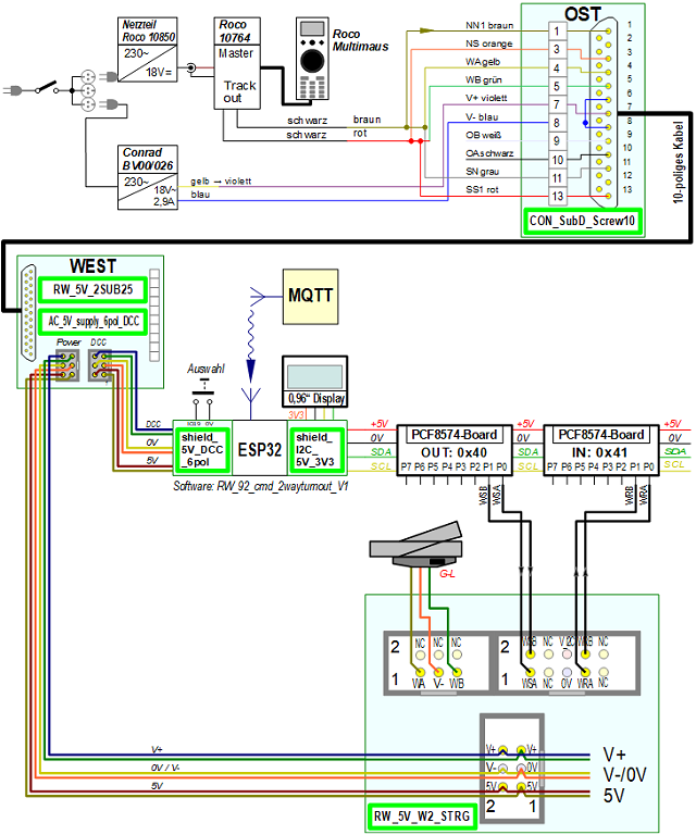
Figure 7 Overall circuit diagram of the RCC-5V system
The upper third of the picture shows the supply of the DCC signal and the AC voltage (“FEED-IN”). The DCC signal for the traction current and the digital switching of the points is generated here with an old Roco-Multimaus, a 230V/18V/2.9A transformer (e.g. BV00/026 from Conrad) is used for the AC voltage supply.
The middle third of the picture shows the connection of the 25-pin connector to the microcontroller (5V and DCC signal) and to the RCC blocks (5V and AC signal). The ESP32 operates two separate I2C buses, one for the 1.56” OLED display (with 3.3V) and the second I2C bus for the PCF8574 boards (with 5V).
Finally, the lower third of the picture shows the control of a two-way switch by an RCC block.
The RCC block receives the switching command "Straight" (set WSA to 0V) or "Branch" (WSB=0V) from the microcontroller, switches the turnout and returns the state of the turnout (WRA=5V, WRB=0V for “Straight” or WRA=0V, WRB=5V for “Branch”). The RCC block also contains two buttons for local switching of the points and two LEDs for local display of the switching status of the points.
You can also see that each RCC block requires a 5V and an AC voltage to switch the points.
| Qty | Value | Footprint | References |
|---|---|---|---|
| 5 | 10k | _kh_library:R_Axial_DIN0204_L3.6mm_D1.6mm_P2.54mm_Vertical_kh | R1, R2, R6, R7, Rs1 |
| 5 | 1k | _kh_library:R_Axial_DIN0204_L3.6mm_D1.6mm_P2.54mm_Vertical_kh | R4, R8, R10, R13, R15 |
| 5 | 1u | _kh_library:C_L4mm_D3mm_P2.54mm_kh | C1, C2, C4, C7, C8 |
| 4 | MountingHole | _kh_library:MountingHole_2.2mm_M2_Pad_TopBottom_kh | H1, H2, H3, H4 |
| 2 | 10k | Resistor_THT:R_Axial_DIN0204_L3.6mm_D1.6mm_P7.62mm_Horizontal | Rs2, Rs3 |
| 2 | 10u | _kh_library:ELKO_L4.32mm_D3.81mm_P2.54mm_kh | C3, C5 |
| 2 | 47 | _kh_library:R_Axial_DIN0204_L3.6mm_D1.6mm_P2.54mm_Vertical_kh | R16, R17 |
| 2 | 47k | _kh_library:R_Axial_DIN0204_L3.6mm_D1.6mm_P2.54mm_Vertical_kh | R9, R14 |
| 2 | BC337 | _kh_library:TO-92_Inline_Wide_custom | Q1, Q2 |
| 2 | SB240 | Diode_THT:D_DO-15_P3.81mm_Vertical_AnodeUp | D1, D2 |
| 2 | Screw_Terminal_01x02_P5 | _kh_library:Screw_Terminal_01x02_P5 | J1, J2 |
| 1 | 100 | Resistor_THT:R_Axial_DIN0204_L3.6mm_D1.6mm_P2.54mm_Vertical | R11 |
| 1 | 10k | _kh_library:Trim_Bourns_3296W_Vertical | RV1 |
| 1 | 1N4007 | _kh_library:D_DO-41_SOD81_P3.81mm_Vertical_AnodeUp_kh | D5 |
| 1 | 1k | Resistor_THT:R_Axial_DIN0204_L3.6mm_D1.6mm_P2.54mm_Vertical | R12 |
| 1 | 220k | Resistor_THT:R_Axial_DIN0204_L3.6mm_D1.6mm_P7.62mm_Horizontal | Rs4 |
| 1 | 33k | _kh_library:R_Axial_DIN0204_L3.6mm_D1.6mm_P2.54mm_Vertical_kh | R3 |
| 1 | 33u/35V | Capacitor_THT:CP_Radial_D8.0mm_P2.50mm | C6 |
| 1 | 47k | _kh_library:R_Axial_DIN0204_L3.6mm_D1.6mm_P7.62mm_Horizontal | R5 |
| 1 | BAT48 | Diode_THT:D_DO-35_SOD27_P2.54mm_Vertical_AnodeUp | D3 |
| 1 | Box_02x03_P2.54_Vertical | _kh_library:Box_02x03_P2.54mm_Vertical_kh | J5 |
| 1 | INA333_Board | _kh_library:INA333_Board | U1 |
| 1 | Jumper_2 | _kh_library:PinSocket_1x02_P2.54mm_Vertical_kh | J3 |
| 1 | LED grün | LED_THT:LED_D3.0mm | D6 |
| 1 | LED rot | LED_THT:LED_D3.0mm | D4 |
| 1 | LM393 | Package_DIP:DIP-8_W7.62mm_Socket_LongPads | U2 |
| 1 | SFH615A | Package_DIP:DIP-4_W7.62mm | U3 |
khartinger/RCC5V
Controlling model railroad components with DCC, MQTT and manually

khartinger/RCC5V
Controlling model railroad components with DCC, MQTT and manually

khartinger/RCC5V
Controlling model railroad components with DCC, MQTT and manually

khartinger/RCC5V
Controlling model railroad components with DCC, MQTT and manually

khartinger/RCC5V
Controlling model railroad components with DCC, MQTT and manually

khartinger/RCC5V
Controlling model railroad components with DCC, MQTT and manually

khartinger/RCC5V
Controlling model railroad components with DCC, MQTT and manually

khartinger/RCC5V
Controlling model railroad components with DCC, MQTT and manually

khartinger/RCC5V
Controlling model railroad components with DCC, MQTT and manually

khartinger/RCC5V
Controlling model railroad components with DCC, MQTT and manually

khartinger/RCC5V
Controlling model railroad components with DCC, MQTT and manually

khartinger/RCC5V
Controlling model railroad components with DCC, MQTT and manually

rjhelms/6502proto
A prototyping board for experimenting with 6502 hardware and software design

KaitoTLex/RoboRyo
This is team1280's replacement for the Robo Rio for more redundant and less annoying controls.


marianobilli/bluetooth-radio-manager
A self-contained, battery-powered box that puts four 2.4 GHz radios under one ESP32-S3, with a small OLED and encoder UI, in a 3D-printed case.

RobertPHeller/RPi-RRCircuits
A collection of circuit designs for various MCUs, not just Raspberry Pis relating to Model Railroading

RobertPHeller/CommandStationsAndBoosters
Command Stations and Boosters

CTXz/Video-Glitch-Array
A collection of glitch art circuits dedicated to VGA signal manipulation
It measures 99.1 × 33 mm and has 2 copper layers, 1.6 mm thick.
49 parts, built around the LM393, SFH615A-3, BC337 and SB240. The full list of its parts is on this page, with links to each part's symbol and footprint where PCBKit's library has them.
From the khartinger/RCC5V repository on GitHub, at the commit this page was made from: the board is fab/kicad/dcc_track_UI_detection_V2/dcc_track_UI_detection_V2.kicad_pcb. PCBKit opens the board in the browser, with nothing to install.
Its repository states no licence, so its author keeps all rights: ask khartinger before reusing the design.