2 layers98 × 63.2 mm

 kermitsgonnakermicide/hate-cbse
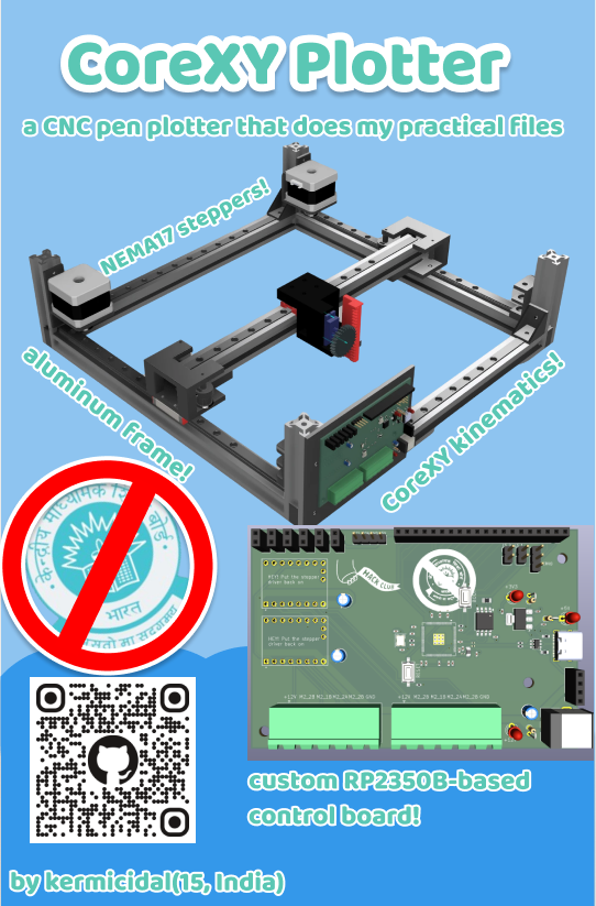
a desk-sized CoreXY pen plotter with a custom RP2350 based motherboard!
Hate cbse is an open-source printed circuit board by kermitsgonnakermicide, from the kermitsgonnakermicide/hate-cbse repository on GitHub. It is a 4-layer board of 101.4 × 68 mm with 73 parts on 103 nets, routed with 640 tracks and 34 vias.
It is built around the RP2350B, TMC2209SILENTSTEPSTICK and W25Q128JVSIQ, with the USBLC6-2SC6 among its other parts. Its parts include 25 capacitors, 16 connectors, 14 resistors, 6 ICs and 3 diodes. It belongs with the robots and motor control and computers and single-board computers boards and the RP2350 boards of this library.


A desk-sized CoreXY pen plotter with a custom RP2350 based motherboard!
for additional context, please view this youtube video
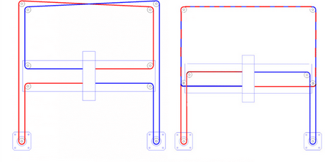
use this image for reference!
this project will be partially self funded out of sheer necessity, so please do not be concerned about any excess BOM cost
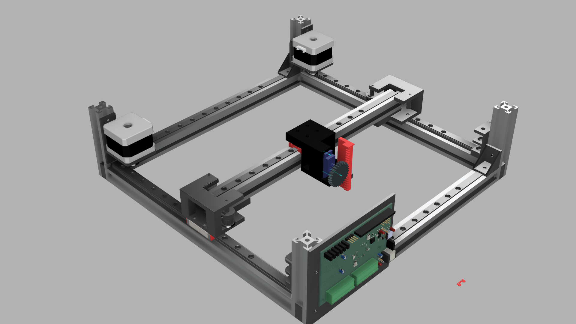
full render
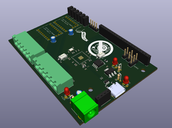
PCB render
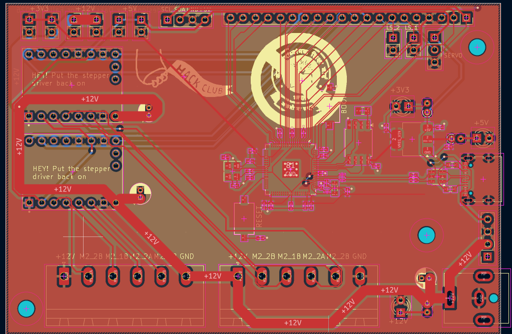
routed PCB
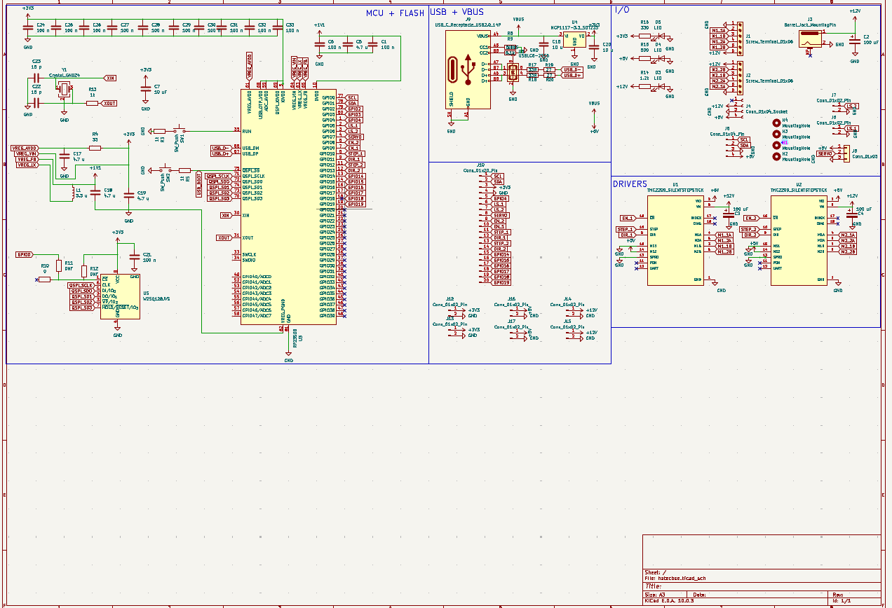
cleaned up schematic
| Qty | Value | Footprint | References |
|---|---|---|---|
| 13 | 100 n | Capacitor_SMD:C_0402_1005Metric | C1, C6, C21, C24, C25, C26, C27, C28, C29, C30, C31, C32, C33 |
| 6 | Conn_01x02_Pin | Connector_PinSocket_2.54mm:PinSocket_1x02_P2.54mm_Vertical | J12, J13, J14, J15, J16, J17 |
| 4 | 4.7 u | Capacitor_SMD:C_0402_1005Metric | C5, C17, C18, C19 |
| 3 | 100 uF | Capacitor_THT:CP_Radial_D4.0mm_P1.50mm | C2, C3, C4 |
| 3 | 1k | Resistor_SMD:R_0402_1005Metric | R3, R5, R13 |
| 3 | LED | LED_THT:LED_D3.0mm | D3, D4, D5 |
| 3 | MountingHole | MountingHole:MountingHole_3.2mm_M3 | H1, H2, H3 |
| 2 | 10 u | Capacitor_SMD:C_0402_1005Metric | C16, C20 |
| 2 | 15 p | Capacitor_SMD:C_0402_1005Metric | C22, C23 |
| 2 | 27 | Resistor_SMD:R_0201_0603Metric | R19, R20 |
| 2 | 33R | Resistor_SMD:R_0402_1005Metric | R17, R18 |
| 2 | 5.1k | Resistor_SMD:R_0603_1608Metric | R8, R9 |
| 2 | Conn_01x02_Pin | Connector_PinHeader_2.54mm:PinHeader_1x02_P2.54mm_Vertical | J6, J7 |
| 2 | LOGO | LOGO | G***, G*** |
| 2 | SW_Push | Button_Switch_SMD:SW_Tactile_SPST_NO_Straight_CK_PTS636Sx25SMTRLFS | SW1, SW2 |
| 2 | Screw_Terminal_01x06 | Connector_Phoenix_MSTB:PhoenixContact_MSTBA_2,5_6-G_1x06_P5.00mm_Horizontal | J1, J2 |
| 2 | TMC2209_SILENTSTEPSTICK | TMC2209_SILENTSTEPSTICK:MODULE_TMC2209_SILENTSTEPSTICK | U1, U2 |
| 1 | 0 | Resistor_SMD:R_0805_2012Metric | R10 |
| 1 | 1.2k | Resistor_THT:R_Axial_DIN0204_L3.6mm_D1.6mm_P1.90mm_Vertical | R14 |
| 1 | 10 uF | Capacitor_SMD:C_0402_1005Metric | C7 |
| 1 | 3.3 u | Inductor_SMD:L_0805_2012Metric | L1 |
| 1 | 33 | Resistor_SMD:R_0201_0603Metric | R4 |
| 1 | 330 | Resistor_THT:R_Axial_DIN0204_L3.6mm_D1.6mm_P1.90mm_Vertical | R16 |
| 1 | 500 | Resistor_THT:R_Axial_DIN0204_L3.6mm_D1.6mm_P1.90mm_Vertical | R15 |
| 1 | Barrel_Jack_MountingPin | Connector_BarrelJack:BarrelJack_CUI_PJ-063AH_Horizontal | J3 |
| 1 | Conn_01x03 | Connector_PinHeader_2.54mm:PinHeader_1x03_P2.54mm_Vertical | J5 |
| 1 | Conn_01x04_Pin | Connector_PinHeader_2.54mm:PinHeader_1x04_P2.54mm_Vertical | J8 |
| 1 | Conn_01x04_Socket | Connector_PinSocket_2.54mm:PinSocket_1x04_P2.54mm_Vertical | J4 |
| 1 | Conn_01x20_Pin | Connector_PinSocket_2.54mm:PinSocket_1x20_P2.54mm_Vertical | J10 |
| 1 | Crystal_GND24 | Crystal:Crystal_SMD_Abracon_ABM8G-4Pin_3.2x2.5mm | Y1 |
| 1 | NCP1117-3.3_SOT223 | Package_TO_SOT_SMD:SOT-223-3_TabPin2 | U4 |
| 1 | RP2350B | Package_DFN_QFN:QFN-80-1EP_10x10mm_P0.4mm_EP3.4x3.4mm | U3 |
| 1 | USBLC6-2SC6 | Package_TO_SOT_SMD:SOT-23-6 | U6 |
| 1 | USB_C_Receptacle_USB2.0_14P | Connector_USB:USB_C_Receptacle_XKB_U262-16XN-4BVC11 | J9 |
| 1 | W25Q128JVS | Package_SO:SOIC-8_5.3x5.3mm_P1.27mm | U5 |

SCREAM325/TI_INFINITY
contains PCB file for PCBway and GCODE files for speaker case.

OpenStickCommunity/Hardware
A collection of hardware designs by members of the OpenStickCommunity


stefanskotte/webadf
Web-based Amiga ADF library that mounts disks to a Gotek over WiFi


AlphaCassiopeiae/8800
Firmware and PCBs for aCassiopeiae, a minature Altair 8800 clone

brandonrc/das4-controller
Open-source RP2350B replacement controller board for the Das Keyboard 4 Professional (KiCad 10)
It measures 101.4 × 68 mm and has 4 copper layers, 1.6 mm thick.
73 parts, built around the RP2350B, TMC2209SILENTSTEPSTICK, W25Q128JVSIQ and USBLC6-2SC6. The full list of its parts is on this page, with links to each part's symbol and footprint where PCBKit's library has them.
From the kermitsgonnakermicide/hate-cbse repository on GitHub, at the commit this page was made from: the board is PCB/hatecbse.kicad_pcb and its schematic PCB/hatecbse.kicad_sch. PCBKit opens the board in the browser, with nothing to install.
Its repository states no licence, so its author keeps all rights: ask kermitsgonnakermicide before reusing the design.