2 layers148.6 × 192.2 mm
Badge
NuttyShell/NuttyBadge
NuttyBadge: A NuttyShell crafted multi-tool. Opensourced Hardawre and Software
169 parts31GPL-3.0

 kaorii-ako/inSomnia1
Adaptive, context-aware wake clock — wakes you while you're already stirring, stays quiet if you're already up. ESP32-S3 + thermal array.
InSomnia is an open-source printed circuit board by kaorii-ako, from the kaorii-ako/inSomnia repository on GitHub. It is a 2-layer board of 100 × 80 mm with 53 parts on 41 nets, routed with 737 tracks and 141 vias.
It is built around the ESP32-S3-WROOM-1-N16R8, 74HC165D and AMS1117-3.3, with the MMBT3904 among its other parts. Its parts include 17 resistors, 14 switches, 8 capacitors, 7 connectors and 4 ICs. It belongs with the lEDs and displays boards and the ESP32 boards of this library.


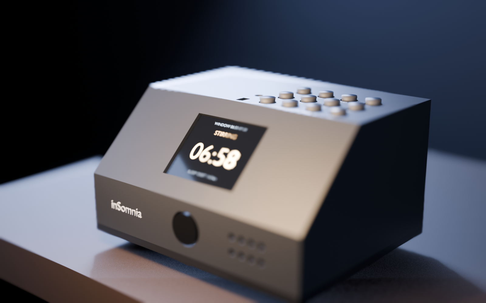
An adaptive, context-aware wake clock. Instead of firing at a fixed timestamp, it wakes you inside a window at a moment you are already stirring — and if you got up before the window even opened, it stays quiet.
Built for Hack Club Forge. Firmware-first, fully offline after WiFi time sync, no cloud service, no audio leaves the device.
| Situation | Behaviour |
|---|---|
| You're already up before the window opens | Alarm is suppressed for the day and logged as "skipped — you were already up" |
| You're carrying sleep debt | The gentle wake is held back by up to 15 min so an early stir doesn't cost you the lie-in. The hard deadline never moves. |
| You start stirring inside the window | Gentle wake begins immediately — soft tone ramping up over several minutes |
| You sleep right through to the hard deadline | Full-intensity alarm, no more waiting |
| A sensor dies or is unplugged | Failsafe: degrades to a plain fixed-time alarm at the deadline. It never fails silent. Even with no WiFi it runs on an internal fallback clock. |
I hate being ripped out of deep sleep at 06:50 exactly when I was finally sleeping well, and I also hate my phone blaring when I’m already in the kitchen making coffee. Both are the same bug: a clock that knows time but not context. I wanted a clock that knows whether I'm in bed and moving — easily measurable with a thermal array — and uses that to pick a kinder moment inside a window, or to stay quiet if I’m already up. I built it for myself, and because a believable demo needs honest numbers, not "AI" marketing.
| col 1 | col 2 | col 3 | col 4 | |
|---|---|---|---|---|
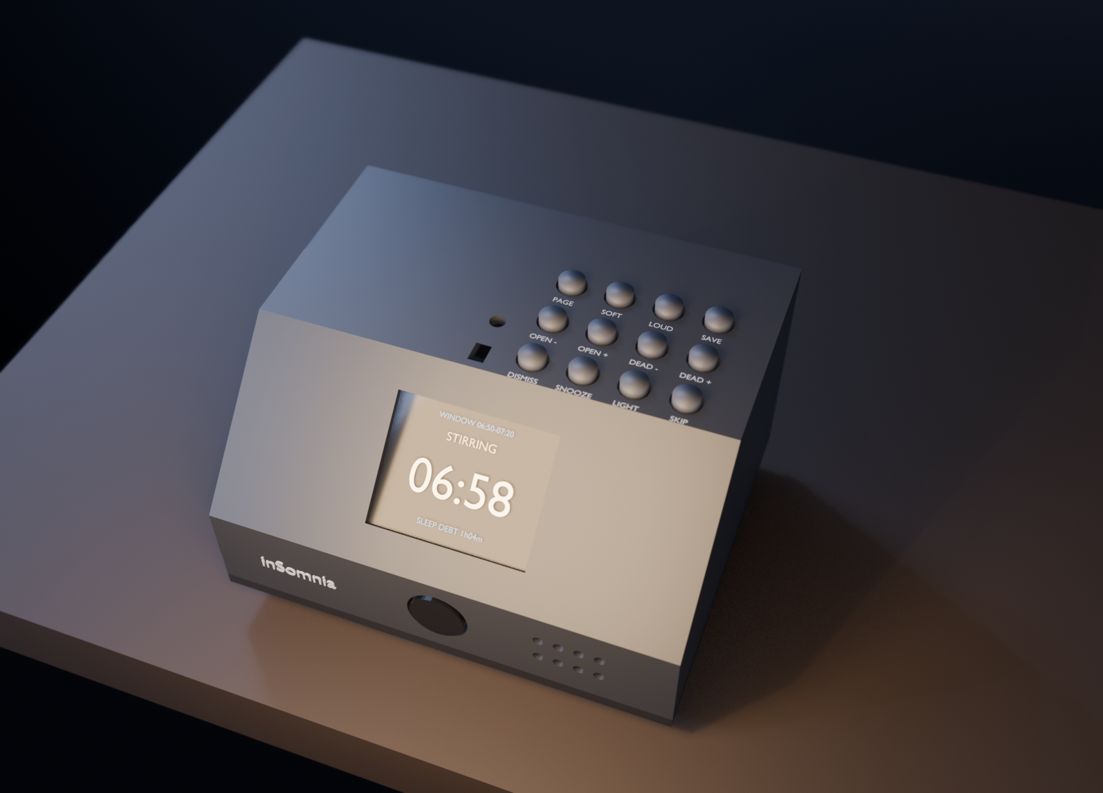
| row 1 (front) | DISMISS | SNOOZE | LIGHT | SKIP |
| row 2 | OPEN − | OPEN + | DEAD − | DEAD + |
| row 3 (back) | PAGE | SOFT | LOUD | SAVE |
Row 1 is what you hit half-asleep. Rows 2 and 3 are setup you do awake: move the window and deadline in 5-minute steps, page through status / window / sleep-debt screens, test the alarm, save to flash. Everything is also on the web UI at http://insomnia.local.
hardware/inSomnia.kicad_pcb, 0805 passives, through-hole tactiles), mount the board on the 4× M2 bosses in hardware/case/inSomnia_case.FCStd, plug modules onto headers: J3 ST7735 TFT, J4 INMP441 mic, J5 MLX90640 thermal (aimed at the bed), J7 optional native USB.cd firmware && pio run -t upload and pio device monitor at 115200. Requires PlatformIO + espressif32@6.5.0.inSomnia-setup (pass insomnia). Join it, open http://192.168.4.1, pick your network + password. Reboots and appears as http://insomnia.local (mDNS). If no WiFi, it still runs on a fallback clock (* beside time) and will still alarm at the deadline.OPEN ± and DEAD ± move times in 5-min steps, PAGE to see them, SAVE to flash. Or on web UI: Settings → Window opens / Hard deadline. roi in Settings crops the bed region if needed.DISMISS stops, SNOOZE (= snoozeMin, default 7) resumes as hard alarm, SKIP is manual "don't bother tonight". Last night's sleep: PAGE → debt screen or web Last night card (TST / efficiency / WASO / SOL — labelled as estimates).countScale is the one calibration — watch Counts this epoch overnight, set so quiet epoch ≈ 0; Body margin and in-bed min pixels for duvet thickness.One sensor does most of the work:
An earlier version used a mattress accelerometer. It was dropped because it needs 1–2 m of I2C cable from the nightstand to the bed, and I2C is spec'd to 400 pF (≈1 m at 100 kHz) against cable that runs 100–240 pF/m.
Two separate pieces of logic sit on top, because they answer different questions:
This matters more than the feature list, so it goes near the top.
The on-device logic is not AI. Cole-Kripke is a weighted moving average with a threshold, published in 1992. The 3-state classifier is thresholds plus hysteresis. Calling either one "AI" would be marketing, not engineering.
Accuracy ceiling. Actigraphy sleep/wake scoring agrees with clinical polysomnography roughly 78–80% of the time. But its specificity for wake is only 0.35–0.64 — it is much better at spotting sleep than wakefulness. Sound-based staging is no better: the best published smartphone-audio model (HomeSleepNet) gets 76.2% overall and 63.4% on wake epochs.
That single fact shaped the design. Alarm suppression is the feature most exposed to a wrong "you're awake" call, so it is not driven by the sleep classifier. It is driven by outOfBed() — no warm mass in the bed region for 3 epochs — which is close to a binary measurement rather than a 64%-accurate inference.
This is not clinical sleep tracking. Without EEG there is no true sleep staging. Consumer trackers systematically overestimate sleep and underestimate wake-after-sleep-onset, worst of all for people who sleep badly. The numbers in the app are estimates and are labelled as such.
One number you must calibrate. Cole-Kripke's weights assume ActiGraph counts, a proprietary unit. Ours are arbitrary units from your own mattress, so countScale in Settings divides ours into that range. The algorithm is validated; this scaling is not. Watch epoch counts overnight and set it so a quiet epoch lands near zero.
Posture is not claimed. The thermal array reports movement and position. Classifying sleeping posture under a duvet at 32×24 is a research problem — the published work that does it used an infrared depth camera with synthetic blanket augmentation. Movement and position are what the sleep model needs, so that is what is built and that is what it says.
Sleep debt is an estimate built on an estimate. Debt is max(0, need − actual) summed over a rolling 14 nights, which is the window research finds matters for current impairment (Van Dongen 2003: 6 h/night for 14 days ≈ two nights of total deprivation). But "actual" comes from Cole-Kripke scoring that under-reports wake — so read it as a trend, not a clinical figure.
No trained model ships yet. A learned audio or thermal classifier is the obvious next step, but a model needs labelled data and there is no polysomnography ground truth here to validate against. The honest path is to ship the validated heuristic, collect feature data, and only then train.
ESP32-S3-WROOM-1-N16R8 — WiFi + BLE 5, native I2S, 8 MB PSRAM, SIMD for future MFCC work. Chosen over the ESP32-C3 because the C3 has no PSRAM and too few GPIO once an I2S microphone is added.
Schematic, pin map, BOM and wiring notes: hardware/HARDWARE.md
BOM with pricing: hardware/inSomnia_bom.csv — ~$68.62 for 1 unit incl. sensors (MLX90640 dominates)
Rendered schematic: hardware/inSomnia_schematic.pdf and images/schematic.png
Gerbers: hardware/inSomnia_gerbers.zip + hardware/fab/
The hero image above is a render from the actual FreeCAD STL (
hardware/case/inSomnia_case_shell.stl, 7,628 verts), not a photo — nothing has been fabricated yet. It is built to the same dimensions as the FreeCAD enclosure below, and the board renders come from the actual KiCad files.
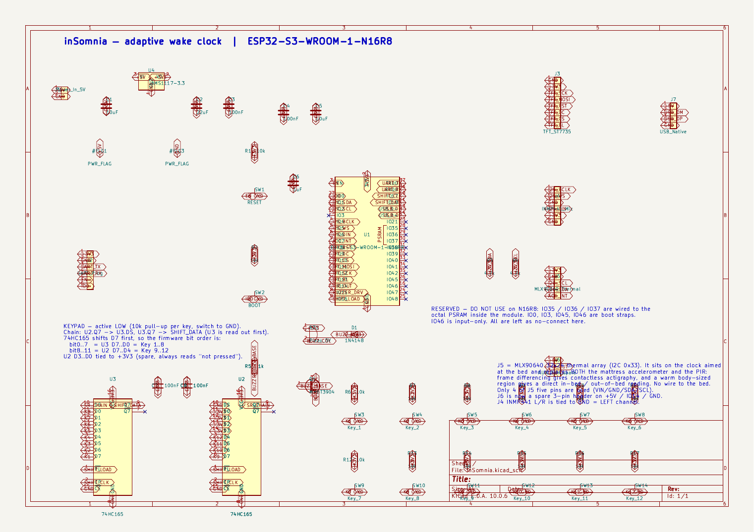
All modules plug onto headers — no soldering to the bed. See hardware/HARDWARE.md pin map for the exact GPIO table and images/routing-front-copper.png for the routed board.
| Header | Module | Wires |
|---|---|---|
| J3 1×08 | ST7735 128×160 TFT | SCK 12, MOSI 11, CS 10, DC 9, RST 8, BL 13 (PWM), +3V3/GND |
| J4 1×06 | INMP441 mic (I2S) | BCLK 4, WS 5, DIN 6, +3V3/GND |
| J5 1×05 | MLX90640 32×24 thermal (I2C) | SDA 1, SCL 2 (4.7k pull-ups), +3V3/GND |
| J6 1×03 | Spare / was PIR | +5V, IO14, GND |
| J7 1×04 | Native USB | D- 19, D+ 20 |
| J1 1×02 | Power 5V in | 5V → AMS1117-3.3 → 3V3 |
| J2 1×06 | UART prog | TX/RX + EN/BOOT tactiles SW1/SW2 |
Parametric case in FreeCAD: hardware/case/ (STEP + STL + .FCStd).
FreeCAD + STEP + STL:
hardware/case/inSomnia_case.FCStd / inSomnia_case_shell.step / inSomnia_case_shell.stl / inSomnia_base_plate.step
Case views: images/case-iso.png images/case-front.png images/case-top.png
The FreeCAD model now embeds the PCB placement so the board sits on the bosses; the Blender render imports the STL directly so they cannot drift (replaced earlier hand-typed dimensions).
Known cosmetic issue: the keypad sits right-of-centre because that is where it is on the PCB. Fixing it means re-laying-out the board; noted for v2.
hardware/inSomnia_gerbers.zipSensor modules (mic, thermal, display) mount on headers rather than being soldered down, so they can be positioned without a bed wire.
PlatformIO + Arduino-ESP32, pinned to espressif32@6.5.0.
cd firmware
pio run              # build
pio run -t upload    # flash
pio device monitor   # serial 115200 — shows [epoch] counts + state + [alarm] transitions
Footprint: RAM 20.1%, Flash 13.6% of a 16 MB part — lots of headroom. Verified 2026-09-17.
No WiFi credentials are stored, so the device opens an access point called inSomnia-setup (password insomnia). Join it, open http://192.168.4.1, pick your network. It reboots and comes back at http://insomnia.local. Without WiFi it still runs on a fallback clock (time shows *) and will still alarm at the hard deadline — it never fails silent.
The web UI gives you the live clock and sleep state, tonight's alarm status, last night's report, live sensor readings (thermal heatmap 32×24, mic RMS/dBFS), and every threshold as an editable setting. Everything stays on your own network — no audio ever leaves the device.
firmware/
  include/ src/
    main.cpp          loop, epoch tick (60s), display render, 12-key handling
    settings.*        NVS-persisted config (window, thresholds, debt)
    net.*             WiFi STA + setup AP, NTP, mDNS, fallback clock
    web_ui.*          HTTP server, dashboard, JSON API (/api/state, /api/thermal, /api/settings)
    display.*         ST7735 128x160 SPI via GPIO matrix
    buzzer.*          LEDC tone + volume (gentle ramp → hard)
    key_matrix.*      74HC165 chain, debounce, edge latch (12 keys)
    thermal.*         MLX90640 -> motion index, in-bed detection, centroid
    mic.*             INMP441 I2S -> RMS / dBFS / loud fraction per epoch
    sleep_model.*     Cole-Kripke + causal 3-state classifier (asleep/stirring/awake)
    sleep_debt.*      rolling 14-night debt, recency-weighted
    alarm.*           window, suppression, escalation, debt shift, failsafe, snooze
Debug mode: serial log each epoch + web Live cards show raw counts, warm pixels, motion index, RMS, state; thresholds are live-editable.
hardware/inSomnia.kicad_pcb — 100 × 80 mm, 2 layer, rounded 3 mm corners.
DRC clean: 0 violations, 0 unconnected items.
| Components | 53 (+4 holes), zero courtyard overlaps |
| Tracks | 737 segments @ 0.20 mm |
| Vias | 141 @ 0.30 mm drill / 0.60 mm pad |
| Copper | GND pour on both layers, islands auto-removed |
| Clearance | 0.20 mm |
| Mounting | 4× 3.2mm NPTH at corners → M2 bosses in case |
Fabrication files are in fab/, zipped as inSomnia_gerbers.zip (Gerbers + Excellon drill + drill map + BOM).
1. The antenna keepout is intentional. A rule area at x 2–50 mm, y 0–6.25 mm keeps copper, tracks and vias out from under the module's antenna, and the courtyard deliberately overhangs the top board edge. DRC flags that overhang as a boundary violation — that is correct RF practice, not a mistake. Verified: no track or via crosses the keepout.
2. There are twelve 0.20 mm holes, and they are not mine. Every via I placed is 0.30 mm. The 0.20 mm holes are the thermal vias built into the stock RF_Module:ESP32-S3-WROOM-1 footprint, under the module's ground pad. Many budget fab processes have a 0.30 mm minimum drill, so this may trigger an upcharge or a rejection. Two options:
The board has not been fabricated or bench-tested. It is DRC-clean, which means the geometry is self-consistent — not that the design is proven. Sanity-checked in #forge and via KiCad/FreeCAD MCP.
countScale ships with a placeholder default and needs per-bed tuning.hardware/HARDWARE.md for the two ways round it.| Qty | Value | Footprint | References |
|---|---|---|---|
| 14 | 10k | Resistor_SMD:R_0805_2012Metric | R1, R2, R6, R7, R8, R9, R10, R11, R12, R13, R14, R15, R16, R17 |
| 4 | 100nF | Capacitor_SMD:C_0805_2012Metric | C3, C4, C7, C8 |
| 2 | 10uF | Capacitor_SMD:C_0805_2012Metric | C1, C5 |
| 2 | 4.7k | Resistor_SMD:R_0805_2012Metric | R3, R4 |
| 2 | 74HC165 | Package_SO:SOIC-16_3.9x9.9mm_P1.27mm | U2, U3 |
| 1 | 1N4148 | Diode_SMD:D_SOD-123 | D1 |
| 1 | 1k | Resistor_SMD:R_0805_2012Metric | R5 |
| 1 | 1uF | Capacitor_SMD:C_0805_2012Metric | C6 |
| 1 | 22uF | Capacitor_SMD:C_0805_2012Metric | C2 |
| 1 | AMS1117-3.3 | Package_TO_SOT_SMD:SOT-223-3_TabPin2 | U4 |
| 1 | AUX_3pin_spare | Connector_PinHeader_2.54mm:PinHeader_1x03_P2.54mm_Vertical | J6 |
| 1 | BOOT | Button_Switch_THT:SW_PUSH_6mm | SW2 |
| 1 | ESP32-S3-WROOM-1-N16R8 | RF_Module:ESP32-S3-WROOM-1 | U1 |
| 1 | INMP441_Mic | Connector_PinHeader_2.54mm:PinHeader_1x06_P2.54mm_Vertical | J4 |
| 1 | Key_1 | Button_Switch_THT:SW_PUSH_6mm | SW3 |
| 1 | Key_10 | Button_Switch_THT:SW_PUSH_6mm | SW12 |
| 1 | Key_11 | Button_Switch_THT:SW_PUSH_6mm | SW13 |
| 1 | Key_12 | Button_Switch_THT:SW_PUSH_6mm | SW14 |
| 1 | Key_2 | Button_Switch_THT:SW_PUSH_6mm | SW4 |
| 1 | Key_3 | Button_Switch_THT:SW_PUSH_6mm | SW5 |
| 1 | Key_4 | Button_Switch_THT:SW_PUSH_6mm | SW6 |
| 1 | Key_5 | Button_Switch_THT:SW_PUSH_6mm | SW7 |
| 1 | Key_6 | Button_Switch_THT:SW_PUSH_6mm | SW8 |
| 1 | Key_7 | Button_Switch_THT:SW_PUSH_6mm | SW9 |
| 1 | Key_8 | Button_Switch_THT:SW_PUSH_6mm | SW10 |
| 1 | Key_9 | Button_Switch_THT:SW_PUSH_6mm | SW11 |
| 1 | MLX90640_Thermal | Connector_PinHeader_2.54mm:PinHeader_1x05_P2.54mm_Vertical | J5 |
| 1 | MMBT3904 | Package_TO_SOT_SMD:SOT-23 | Q1 |
| 1 | Piezo_5V | Buzzer_Beeper:Buzzer_TDK_PS1240P02BT_D12.2mm_H6.5mm | BZ1 |
| 1 | Power_In_5V | Connector_PinHeader_2.54mm:PinHeader_1x02_P2.54mm_Vertical | J1 |
| 1 | RESET | Button_Switch_THT:SW_PUSH_6mm | SW1 |
| 1 | TFT_ST7735 | Connector_PinHeader_2.54mm:PinHeader_1x08_P2.54mm_Vertical | J3 |
| 1 | UART_Prog | Connector_PinHeader_2.54mm:PinHeader_1x06_P2.54mm_Vertical | J2 |
| 1 | USB_Native | Connector_PinHeader_2.54mm:PinHeader_1x04_P2.54mm_Vertical | J7 |
NuttyShell/NuttyBadge
NuttyBadge: A NuttyShell crafted multi-tool. Opensourced Hardawre and Software

Marcel-B/Synth
Die beiden Browser-Synthesizer aus Tonwerk (YuE UI) als Plugins für Logic Pro: Tonwerk Analog und Tonwerk FM, jeder mit Delay und Hall und eigenen Werksklängen.


rico-x/GemilaiMate
Gemilai 3007Z DIY carrier and standalone firmware. Prototype: hardware not assembled or tested.

westlicht/performer-hardware
PER|FORMER Eurorack Sequencer - Hardware Design Files


lennartquerter/euro-rack-synth
Lenimal Github for DIY for a Eurorack Synth
It measures 100 × 80 mm and has 2 copper layers, 1.6 mm thick.
53 parts, built around the ESP32-S3-WROOM-1-N16R8, 74HC165D, AMS1117-3.3 and MMBT3904. The full list of its parts is on this page, with links to each part's symbol and footprint where PCBKit's library has them.
From the kaorii-ako/inSomnia repository on GitHub, at the commit this page was made from: the board is hardware/inSomnia.kicad_pcb and its schematic hardware/inSomnia.kicad_sch. PCBKit opens the board in the browser, with nothing to install.
Its repository states no licence, so its author keeps all rights: ask kaorii-ako before reusing the design.