Skip to the content
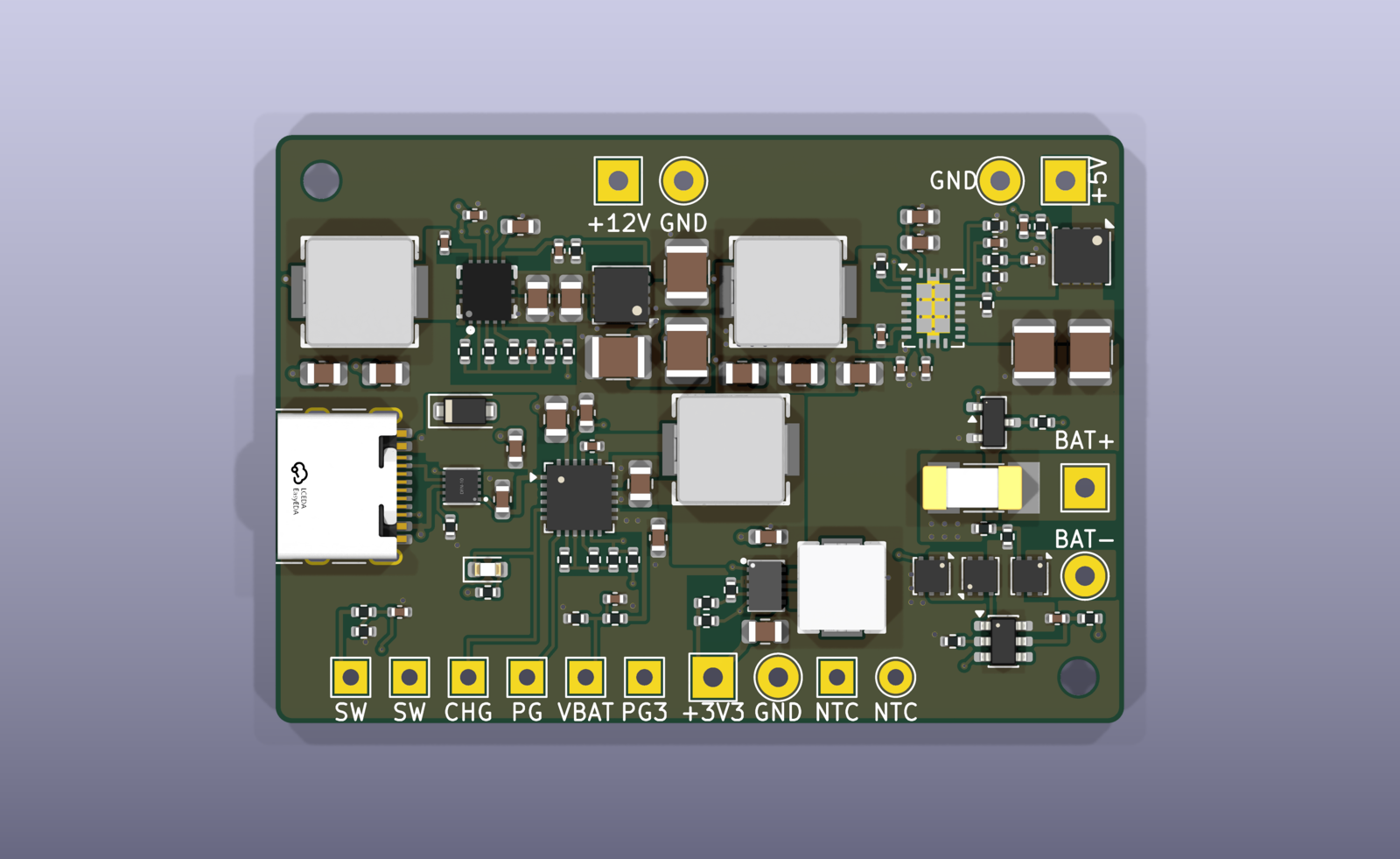
4 layers52 × 36 mmMinipc power, the printed circuit board in 3D

Small power board for MCU-based emulator builds (Pico / ESP32 class with a 12 V 5" LCD). Runs from USB-C or a 1S2P 18650 pack, charges the pack whenever USB-C is plugged in, and supplies 12 V, 5 V and 3.3 V.

Size
52 × 36 mm
Copper layers
4
Thickness
1.6 mm
Parts
106
Nets
75
Pads
378
Tracks, vias
316, 161
Pours
31
Routed
Yes
KiCad
KiCad 10.0 (file 20260206)
Created
25 Oct 2026
Updated
25 Oct 2026

Overview

Minipc power is an open-source printed circuit board by jvanderberg, from the jvanderberg/minipc-power repository on GitHub. It is a 4-layer board of 52 × 36 mm with 106 parts on 75 nets, routed with 316 tracks and 161 vias.

It is built around the CH224Q, HY2113-MB1A and TPS61088-Q1RHL, with the TPS63802DLA, DMN1004UFV-7 and CSD25404Q3 among its other parts. Its parts include 38 capacitors, 30 resistors, 17 connectors, 6 ICs and 6 transistors.

Main components

7

README

README.md

minipc-power

Small power board for MCU-based emulator builds (Pico / ESP32 class with a 12 V 5" LCD). Runs from USB-C or a 1S2P 18650 pack, charges the pack whenever USB-C is plugged in, and supplies 12 V, 5 V and 3.3 V.

routed board

Features

  • USB-C PD input: requests 9 V (CH224Q), falls back to 5 V on non-PD chargers; TVS on VBUS.
  • Charger: BQ25606 standalone switching charger, 1.44 A charge to 4.2 V, 1.9 A input limit. Power path: the board runs from USB even with a dead or missing pack. NTC input for charge-temperature limits.
  • Battery protection for bare cells: HY2113 protector (over-charge 4.28 V, over-discharge 2.80 V, over-current, short circuit), 10 A fuse, reverse-polarity FET.
  • Outputs, all switched together by one on/off switch (off by default):
    • 12 V, 0.5 A: TPS61178 synchronous boost with output disconnect (for the LCD)
    • 5 V, 2.5 A: TPS61088-Q1 synchronous boost with a soft-start load switch
    • 3.3 V, 1.5 A: TPS63802 buck-boost (regulated across the whole battery range)
  • Power budget: 15 W combined as a peak; about 10-12 W continuous in a closed box (see docs/thermal.md).
  • Solder pads for everything: battery, outputs, on/off switch, NTC, status (charging, power good, 3.3 V good, battery voltage sense).
  • Board: 52 x 36 mm, 4 layers (JLCPCB JLC04161H-7628), parts from LCSC; every part has its datasheet link.

Status

Design reviewed, not yet built. Bench checks to run first: docs/power-design.md s9 and docs/review-2026-10-24.md. hardware/production/ predates the latest board changes: regenerate it before ordering.

Files

  • hardware/ - KiCad 10 project (schematic, board, symbols, footprints, 3D models)
  • tools/ - the schematic and board are generated by these scripts; edit them, not the KiCad files: python3 tools/gen_schematic.py && bash tools/build_board.sh (needs KiCad 10 and kicad-skills)
  • docs/requirements.md - requirements and architecture (start here)
  • docs/power-design.md - every component value and where it comes from
  • docs/thermal.md - heat budget
  • docs/review-2026-10-24.md - design review: fixed, open, owner decisions, bench checks
  • docs/layout-compliance.md - each converter's layout against its datasheet
  • docs/skill-gaps.md - problems found in the kicad-skills plugin while designing this board

Parts

106
QtyValueFootprintReferences
7100nFCapacitor_SMD:C_0402_1005MetricC8, C11, C23, C24, C32, C35, C36
510uFCapacitor_SMD:C_0805_2012MetricC3, C5, C20, C21, C22
4100kResistor_SMD:R_0402_1005MetricR16, R22, R26, R28
41uFCapacitor_SMD:C_0603_1608MetricC1, C2, C25, C26
322uFCapacitor_SMD:C_0805_2012MetricC9, C10, C34
322uFCapacitor_SMD:C_1210_3225MetricC17, C18, C19
3DMN1004UFVPackage_SON:Diodes_PowerDI3333-8Q1, Q2, Q3
3GNDTestPoint:TestPoint_THTPad_D2.5mm_Drill1.2mmJ15, J16, J17
210kResistor_SMD:R_0402_1005MetricR9, R23
21MResistor_SMD:R_0402_1005MetricR10, R30
21kResistor_SMD:R_0402_1005MetricR6, R27
21uFCapacitor_SMD:C_0402_1005MetricC37, C38
24.7uFCapacitor_SMD:C_0805_2012MetricC14, C15
24.7uFCapacitor_SMD:C_0603_1608MetricC7, C12
247uFCapacitor_SMD:C_1210_3225MetricC30, C31
269.8kResistor_SMD:R_0402_1005MetricR18, R20
2CSD25404Q3Package_SON:VSON-8_3.3x3.3mm_P0.65mm_NexFETQ4, Q5
2M2MountingHole:MountingHole_2.2mm_M2H1, H2
1+12V OUTTestPoint:TestPoint_THTPad_2.5x2.5mm_Drill1.2mmJ6
1+3V3 OUTTestPoint:TestPoint_THTPad_2.5x2.5mm_Drill1.2mmJ8
1+5V OUTTestPoint:TestPoint_THTPad_2.5x2.5mm_Drill1.2mmJ7
10.47uHJLCImport:FXL0530-R47-ML4
11.8nFCapacitor_SMD:C_0402_1005MetricC13
1100Resistor_SMD:R_0402_1005MetricR7
110AFuse:Fuse_Littelfuse-NANO2-451_453F1
110nFCapacitor_SMD:C_0402_1005MetricC27
110uFCapacitor_SMD:C_0603_1608MetricC6
1162kResistor_SMD:R_0402_1005MetricR12
1169kResistor_SMD:R_0402_1005MetricR11
11uHJLCImport:FXL0630-1R0-ML3
12.2uHJLCImport:FXL0630-2R2-ML1
1220kResistor_SMD:R_0402_1005MetricR19
122nFCapacitor_SMD:C_0402_1005MetricC16
122uFCapacitor_SMD:C_0603_1608MetricC33
1249Resistor_SMD:R_0402_1005MetricR2
1267kResistor_SMD:R_0402_1005MetricR17
128.7kResistor_SMD:R_0402_1005MetricR21
12N7002Package_TO_SOT_SMD:SOT-23Q6
12kResistor_SMD:R_0402_1005MetricR8
13.3uHJLCImport:FXL0630-3R3-ML2
130.9kResistor_SMD:R_0402_1005MetricR5
133pFCapacitor_SMD:C_0402_1005MetricC29
13V3_PGTestPoint:TestPoint_THTPad_2.0x2.0mm_Drill1.0mmJ14
144.2kResistor_SMD:R_0402_1005MetricR15
1470Resistor_SMD:R_0402_1005MetricR3
1470kResistor_SMD:R_0402_1005MetricR29
147nFCapacitor_SMD:C_0402_1005MetricC4
15.23kResistor_SMD:R_0402_1005MetricR4
1511kResistor_SMD:R_0402_1005MetricR24
16.8kResistor_SMD:R_0402_1005MetricR1
1680pFCapacitor_SMD:C_0402_1005MetricC28
1732kResistor_SMD:R_0402_1005MetricR13
180.6kResistor_SMD:R_0402_1005MetricR14
191kResistor_SMD:R_0402_1005MetricR25
1BAT+TestPoint:TestPoint_THTPad_2.5x2.5mm_Drill1.2mmJ2
1BAT-TestPoint:TestPoint_THTPad_D2.5mm_Drill1.2mmJ3
1BQ25606Package_DFN_QFN:Texas_RGE0024H_VQFN-24-1EP_4x4mm_P0.5mm_EP2.7x2.7mm_ThermalViasU2
1CH224QJLCImport:CH224Q_C46061833U1
1CHGTestPoint:TestPoint_THTPad_2.0x2.0mm_Drill1.0mmJ11
1EN (switch)TestPoint:TestPoint_THTPad_2.0x2.0mm_Drill1.0mmJ9
1HY2113-MB1APackage_TO_SOT_SMD:SOT-23-6U3
1NTCTestPoint:TestPoint_THTPad_2.0x2.0mm_Drill1.0mmJ4
1NTC-TestPoint:TestPoint_THTPad_D2.0mm_Drill1.0mmJ5
1PG_CHGTestPoint:TestPoint_THTPad_2.0x2.0mm_Drill1.0mmJ12
1SMF12ADiode_SMD:D_SOD-123FD1
1TPS61088-Q1Package_DFN_QFN:Texas_VQFN-RHL-20_ThermalViasU5
1TPS61178JLCImport:TPS61178RNWRU4
1TPS63802JLCImport:TPS63802DLARU6
1USB-C HRO TYPE-C-31-M-12Connector_USB:USB_C_Receptacle_HRO_TYPE-C-31-M-12J1
1VBAT_SENSETestPoint:TestPoint_THTPad_2.0x2.0mm_Drill1.0mmJ13
1VSYS (switch)TestPoint:TestPoint_THTPad_2.0x2.0mm_Drill1.0mmJ10
1redLED_SMD:LED_0603_1608MetricLED1

More from jvanderberg/minipc-power

3
  • 10 layers110.8 × 90.2 mmWebench d35-view, the printed circuit board in 3D

    Webench d35-view

    jvanderberg/minipc-power

    Small power board for MCU-based emulator builds (Pico / ESP32 class with a 12 V 5" LCD). Runs from USB-C or a 1S2P 18650 pack, charges the pack whenever USB-C is plugged in, and supplies 12 V, 5 V and 3.3 V.

    24 parts
  • 10 layersWebench d33, the printed circuit board in 3D

    Webench d33

    jvanderberg/minipc-power

    Small power board for MCU-based emulator builds (Pico / ESP32 class with a 12 V 5" LCD). Runs from USB-C or a 1S2P 18650 pack, charges the pack whenever USB-C is plugged in, and supplies 12 V, 5 V and 3.3 V.

    24 parts
  • 10 layersWebench d36, the printed circuit board in 3D

    Webench d36

    jvanderberg/minipc-power

    Small power board for MCU-based emulator builds (Pico / ESP32 class with a 12 V 5" LCD). Runs from USB-C or a 1S2P 18650 pack, charges the pack whenever USB-C is plugged in, and supplies 12 V, 5 V and 3.3 V.

    14 parts

Similar boards

  • 4 layers99.5 × 65.1 mmRadar2, the printed circuit board in 3D

    Radar2

    chadayas/radar

    through-wall radar KiCad design files and C++ firmware

    135 parts
  • 4 layers52.5 × 80 mmCharger compare, the printed circuit board in 3D

    Charger compare

    WillB97/lipo-chg-eval-pcb

    BQ25792/MP2759 LiPo Charger Evaluation Board

    110 parts2
  • 4 layers100 × 60 mmPocKETlab, the printed circuit board in 3D

    PocKETlab

    bublinak/PocKETlab

    127 partsMIT
  • 4 layers96.3 × 71 mmEnvDaqBox, the printed circuit board in 3D

    EnvDaqBox

    Yongci/EnvDaqBox-PCB

    This is a development board designed for automated flower watering or smart agriculture, primarily used for controlling the watering and lighting systems. It is currently under development.

    96 partsApache-2.0
  • 2 layers100 × 50 mmPd power supply, the printed circuit board in 3D

    Pd power supply

    ziteh/pd-power-supply

    Adjustable power supply based on USB PD (WIP)

    110 partsCERN-OHL-P-2.0
  • 2 layers84 × 22 mmLi Po charger, the printed circuit board in 3D

    Li Po charger

    e-tinkers/18650_battery_charger

    This is a battery charger for Li-Po and modified 18650 Battery Charger with a 3.3/5v LDO.

    36 parts5CC0-1.0
  • 2 layers90 × 100 mmHost shell, the printed circuit board in 3D

    Host shell

    shapoco/wildcardboy

    Handheld Game Console with Replaceable MCU

    241 parts5

Questions

How big is the Minipc power PCB?

It measures 52 × 36 mm and has 4 copper layers, 1.6 mm thick.

What parts does the Minipc power use?

106 parts, built around the CH224Q, HY2113-MB1A, TPS61088-Q1RHL and TPS63802DLA. The full list of its parts is on this page, with links to each part's symbol and footprint where PCBKit's library has them.

Where can I download the Minipc power KiCad files?

From the jvanderberg/minipc-power repository on GitHub, at the commit this page was made from: the board is hardware/minipc-power.kicad_pcb and its schematic hardware/minipc-power.kicad_sch. PCBKit opens the board in the browser, with nothing to install.

Can I use the Minipc power design in my own project?

Its repository states no licence, so its author keeps all rights: ask jvanderberg before reusing the design.