Skip to the content
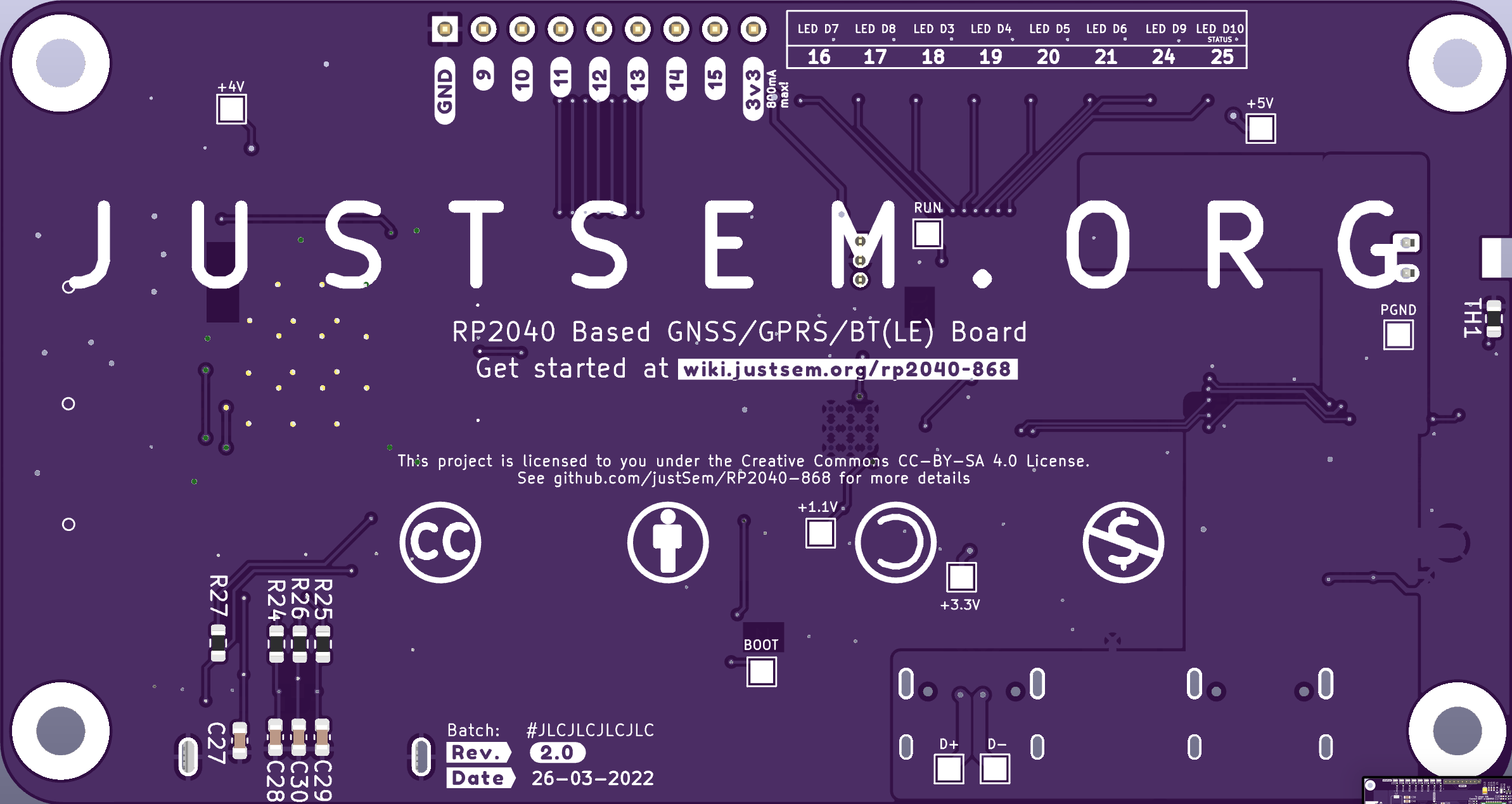
2 layers99.6 × 53 mmRP2040GPSTracker, the printed circuit board in 3D

RP2040GPSTracker

justsem/RP2040-86811

A GPRS/GNSS/BTLE and LiPo/Li-ion charger integrated Pi Pico on credit-card format.

Size
99.6 × 53 mm
Copper layers
2
Thickness
1 mm
Parts
176
Nets
154
Pads
533
Tracks, vias
1,030, 171
Pours
20
Routed
Yes
KiCad
KiCad 6 (file 20211014)
Created
1 Mar 2022
Updated
30 Mar 2022

Overview

RP2040GPSTracker is an open-source printed circuit board by justsem, from the justsem/RP2040-868 repository on GitHub, published under the CC-BY-SA-4.0 licence. It is a 2-layer board of 99.6 × 53 mm with 176 parts on 154 nets, routed with 1,030 tracks and 171 vias.

It is built around the SI2319CDS and ESDA6V1-5W6. Its parts include 51 resistors, 40 capacitors, 10 diodes, 7 connectors and 2 transistors. It belongs with the power boards and the RP2040 boards of this library.

Main components

2

README

README.md

BE AWARE This project is still in active development, I'm still in the process of ordering and testing prototypes, so the latest version is not tested to be fully-working as of yet.

RP2040-868

A GPRS/GNSS/BTLE and LiPo/Li-ion charger integrated Pi Pico on credit-card format.
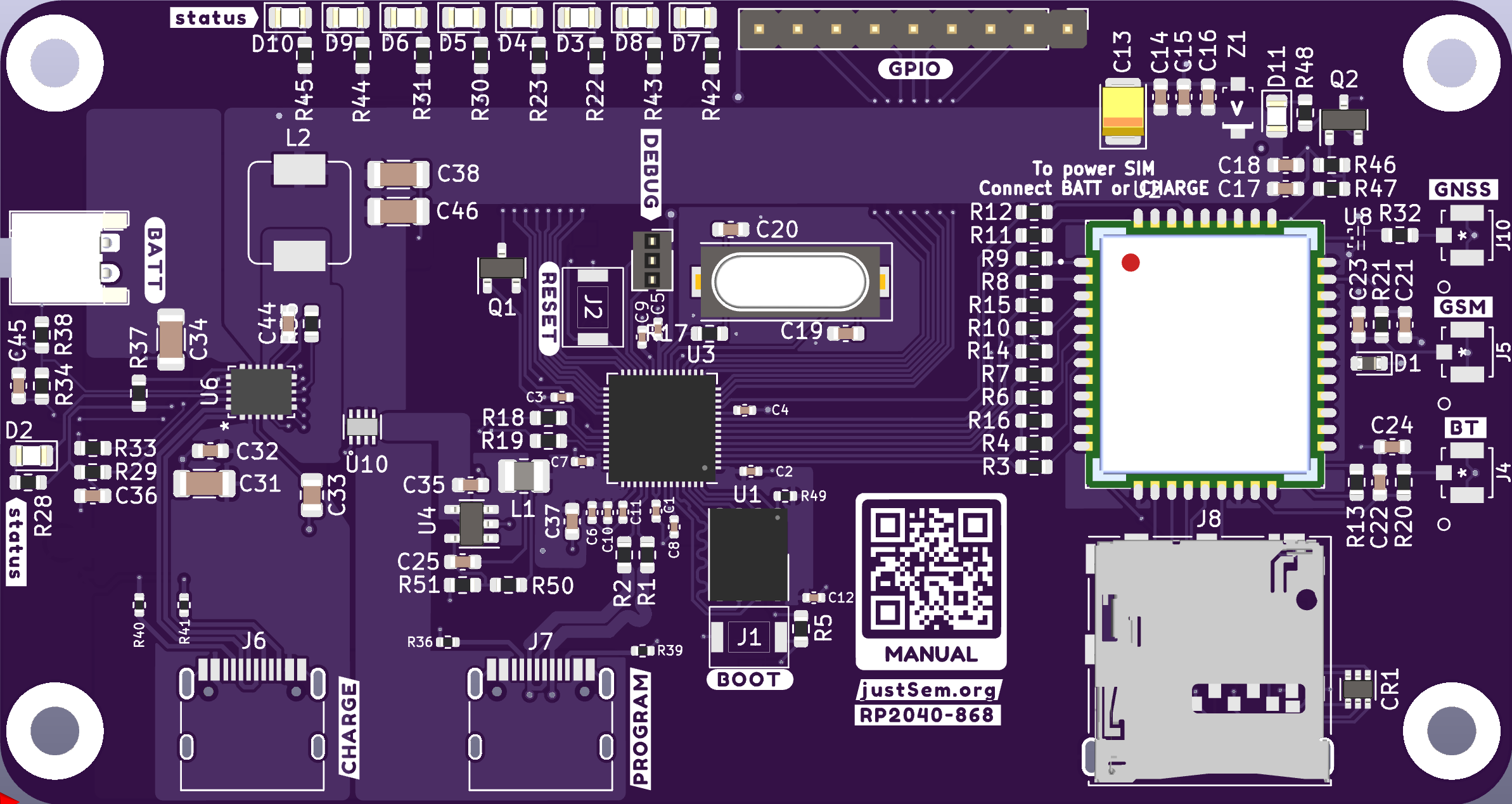
Board Front Board Rear Size: 99x50mm

Title says it all!

This is a fully integrated RP2040-based board featuring the following:

  • GPRS Enabled (with microSIM card format)
  • GNSS (GPS, GLONASS, BEIDOU)
  • BT(LE)
  • Integrated LiPo/Li-ion charging circuit.
  • USB-C (in USB2.0 mode) ports for future proofing.
  • Programmable as if it's a "normal" RPI Pico
  • Auto-switching power source: In case you connect both the Battery/USB Power and the USB-Program port, the device will automatically switch it's power source to the "PROG" port.

The boards origin

Me and my friends work with GPS trackers a lot, for various purposes. For a while we used cheap AliExpress trackers, but we felt they couldn't be fully trusted. They're dirt-cheap but in return, closed-source. We had absolutely no guarantee that it won't secretly send our data back to China. So I decided to make our own version.

What started as a simple board grew out to be a fully-programmable board. Since most of our group favor Python over C++ (simply because we're more used to Python :) ) we went with an RP2040

Board Details

  • The charger is a Monolithic Power MP2624
  • The GPRS/GNSS/BT(LE) Module is a SIMCom SIM868
  • At the heart of the board you'll find a Raspberry Pi RP2040

Quick Start

If you have the board you can simply access the programming mode by going through the following steps:

  1. Connect a USB-C cable to the port labeled PROG
  2. Press and hold the RESET button
  3. Pres and hold the PROG button
  4. Release the RESET button
  5. Release the PROG button

The device should now present itself as removable storage to your system, allowing you to upload/download files to/from it. You can use the provided code for some working examples.

Costs

I haven't exactly calculated the costs. But for the 5 prototypes I built I spent roughly 30 euro's/board. This includes overhead as some components had a minimium buy of 100 pieces. So the exact costs are most likely below the number mentioned above.

Planned Future

The plan is to make some changes in the future, these changes could be:

Move to another Cellular Chip

The SimCom chips can have 2A peak currents, which require a pcb designed to accomodate said currents.

Support for more modern cellular acces

GPRS is soon to be EOL. But at the time of writing there are no subsitutes which are worth the price in this project. 3G chips are available, but those networks are to be turned off 03-2022 in this country, which makes them not suitable for this project. LTE-M (or other IoT bands) are still only available to commercial customers, chips for these networks are readily available but sadly not usable in this country.

For now it's waiting to see if any decent substitute will become available in the upcoming months.

Support NanoSIM

While it's theoretically possible with Rev 1.1 of the board, it hasn't been tested as of yet.

F.A.Q.

Do you sell these boards?

No. I have no commercial interest with this project, but I might have spares at times, which I might be willing to send as long as you cover the costs. Feel free to reach out if you're interested.

Can you implement feature X?

You're free to implement any software feature yourself. The boards are programmable for a reason :)

The board files can be altered using KiCad, enabling you to make hardware changes as well.

I found a flaw

Great! Please open an issue and describe what you found.

DISCLAIMER

I am in no way a professional PCB designer - this design could be flawed without me being aware of it. I make things as a hobby without any guarantee on functionality, compatibility or reliability. As stated in the License this product comes without any guarantee.

CHANGELOG

Rev 3.1

  • Reversed change in crystal due to availability issues.
  • Swapped SOIC-8 Flash for WSON variant.
  • Removed SIM from PROG power-stage - no suitable DC-DC converter available for a reasonable price to do 5V->4V @ 2A.
  • In order to access the SIM868 whilst programming, it is now required to either connect a battery, or an USB-cable to the CHARGE power-stage.

Rev 2.0

  • Swapped 100nF caps for 0402 to get them closer to the MCU.
  • Moved around power-stage parts for thermal performance.
  • Re-implemented USB connections to comply with USB Spec (impedance issues).

Parts

176
QtyValueFootprintReferences
111kResistor_SMD:R_0603_1608MetricR3, R4, R5, R6, R7, R8, R9, R10, R11, R12, R17
10100nFCapacitor_SMD:C_0402_1005MetricC1, C2, C3, C4, C5, C6, C7, C8, C9, C12
9TestPointTestPoint:TestPoint_Pad_1.5x1.5mmTP1, TP2, TP3, TP4, TP5, TP6, TP7, TP8, TP9
6BLUELED_SMD:LED_0805_2012MetricD4, D5, D6, D9, D10, D11
510uFCapacitor_SMD:C_0603_1608MetricC14, C17, C35, C36, C37
420Resistor_SMD:R_0603_1608MetricR23, R30, R31, R44
422pFCapacitor_SMD:C_0603_1608MetricC25, C28, C29, C30
45.1kResistor_SMD:R_0402_1005MetricR36, R39, R40, R41
456Resistor_SMD:R_0603_1608MetricR22, R42, R43, R48
4DNFCapacitor_SMD:C_0603_1608MetricC21, C22, C23, C24
4MountingHoleMountingHole:MountingHole_3.2mm_M3_PadH1, H2, H3, H4
30RResistor_SMD:R_0603_1608MetricR20, R21, R32
3100kResistor_SMD:R_0603_1608MetricR35, R37, R50
3100nFCapacitor_SMD:C_0603_1608MetricC18, C27, C45
310kResistor_SMD:R_0603_1608MetricR13, R18, R19
322Resistor_SMD:R_0603_1608MetricR24, R25, R26
322uFCapacitor_SMD:C_1206_3216MetricC34, C38, C46
35.6kResistor_SMD:R_0603_1608MetricR14, R15, R16
3REDLED_SMD:LED_0805_2012MetricD3, D7, D8
21uFCapacitor_SMD:C_0402_1005MetricC10, C11
227.4Resistor_SMD:R_0603_1608MetricR1, R2
227pCapacitor_SMD:C_0603_1608MetricC19, C20
24.7kResistor_SMD:R_0603_1608MetricR27, R47
2NetTie_2NetTie:NetTie-2_SMD_Pad0.5mmNT2, NT3
2RResistor_SMD:R_0603_1608MetricR34, R38
2Si2319CDSPackage_TO_SOT_SMD:SOT-23Q1, Q2
1RP2040-868Graphics:12-ca
1RP2040-868Graphics:gpio-ca
1RP2040-868Graphics:9-ca
1RP2040-868Graphics:14-ca
1RP2040-868Graphics:rev-cc-ha
1RP2040-868Graphics:rp2040-868-re
1RP2040-868Graphics:3v3-lc-ca
1RP2040-868Graphics:batt-ca
1RP2040-868Graphics:status-lc-ha-left
1RP2040-868Graphics:r2_0-ca
1RP2040-868Graphics:gnd-ca
1RP2040-868Graphics:debug-ha
1RP2040-868Graphics:11-ca
1RP2040-868Graphics:10-ca
1RP2040-868Graphics:date-cc-ha
1RP2040-868Graphics:charge-fs
1RP2040-868Graphics:program-fs
1RP2040-868Graphics:15-ca
1RP2040-868Graphics:wikiref-re
1RP2040-868Graphics:boot-ca
1RP2040-868Graphics:jsorg-fs
1RP2040-868Graphics:bt-re
1RP2040-868Graphics:gsm-re
1RP2040-868Graphics:13-ca
1RP2040-868Graphics:reset-ca
1RP2040-868Graphics:status-lc-ha
1RP2040-868Graphics:gnss-re
1100Resistor_SMD:R_0603_1608MetricR45
1100/0.2Resistor_SMD:R_0603_1608MetricR28
1100uFCapacitor_Tantalum_SMD:CP_EIA-3528-15_AVX-HC13
110KResistor_SMD:R_0603_1608MetricTH1
110pFCapacitor_SMD:C_0603_1608MetricC16
116.16kResistor_SMD:R_0603_1608MetricR33
11uFCapacitor_SMD:C_0603_1608MetricC32
11uHInductor_SMD:L_Sumida_CDMC6D28_7.25x6.5mmL2
11uHInductor_SMD:L_1008_2520MetricL1
122kResistor_SMD:R_0603_1608MetricR51
12822541-1SIMCard:2822541-1J8
12kResistor_SMD:R_0603_1608MetricR29
133pFCapacitor_SMD:C_0603_1608MetricC15
14.7uFCapacitor_SMD:C_0805_2012MetricC33
14.7uFCapacitor_SMD:C_1206_3216MetricC31
1470nFCapacitor_SMD:C_0603_1608MetricC44
147kResistor_SMD:R_0603_1608MetricR46
1BATTERYConnector_JST:JST_PH_S2B-PH-K_1x02_P2.00mm_HorizontalJ9
1BOOTSELButton_Switch_SMD:SW_SPST_ALPS_SKRKAEE020J1
1BT(LE)Antenna:U.FL-R-SMT10J4
1CrystalCrystal:Crystal_SMD_HC49-SDY1
1DEBUGConnector_PinSocket_1.27mm:PinSocket_1x03_P1.27mm_VerticalJ3
1DNFResistor_SMD:R_0402_1005MetricR49
1D_TVSDiode_SMD:D_0603_1608MetricD1
1ESDA6V1-5W6Package_TO_SOT_SMD:SOT-363_SC-70-6CR1
1GNSSAntenna:U.FL-R-SMT10J10
1GPIO9-15Connector_PinHeader_2.54mm:PinHeader_1x09_P2.54mm_VerticalJ11

The 157 most common of 176 parts.

Similar boards

  • 2 layers60 × 150 mmPhone, the printed circuit board in 3D

    Phone

    TheEinfachFelix/CampPhone

    Warum habe ich mich dagegen entschieden, das Sim Modul selber zu implementieren? Ich habe kein Chip gefunden, der günstiger als das fertige Modul war, und ein Datenblatt in Englischer Sprache hat.

    137 parts
  • 2 layers25.5 × 27.9 mmMicroduino SIM shield DE, the printed circuit board in 3D

    Microduino SIM shield DE

    r-map/rmap

    rete monitoraggio ambientale partecipativo documentation at https://doc.rmap.cc

    20 parts55
  • 2 layers104 × 129 mmModbus master, the printed circuit board in 3D

    Modbus master

    magnusbpt/Modbus-wireless

    83 parts
  • 4 layers19 × 111.1 mmGliss main, the printed circuit board in 3D

    Gliss main

    BelaPlatform/gliss-hardware

    You can find the source KiCad files for the Gliss module in this repository. This project is open hardware and under the Creative Commons Share Alike license 4.0.

    107 parts18
  • 2 layers115 × 115 mmDrone, the printed circuit board in 3D

    Drone

    rmingon/drone-uwb

    Drone design for automatic position in space with UWB

    49 parts13
  • 2 layers100 × 100 mmBQ76pl455a, the printed circuit board in 3D

    BQ76pl455a

    g-rahul/BQ76PL455A-EVM-Clone

    This respository contains low cost design files for BQ76PL455A-EVM Clone.

    255 parts5
  • 2 layers40 × 61 mmUWB Fly Drone, the printed circuit board in 3D

    UWB Fly Drone

    DynamicWhiteHat/Orbit

    An ESP-32 powered drone that follows you

    81 parts4
  • 2 layers101.5 × 25.5 mmVfd, the printed circuit board in 3D

    Vfd

    Jana-Marie/HCS-12SS59T-HW

    Otter

    60 parts2

Questions

How big is the RP2040GPSTracker PCB?

It measures 99.6 × 53 mm and has 2 copper layers, 1 mm thick.

What parts does the RP2040GPSTracker use?

176 parts, built around the SI2319CDS and ESDA6V1-5W6. The full list of its parts is on this page, with links to each part's symbol and footprint where PCBKit's library has them.

Where can I download the RP2040GPSTracker KiCad files?

From the justsem/RP2040-868 repository on GitHub, at the commit this page was made from: the board is Board Files/KiCad/RP2040GPSTracker.kicad_pcb and its schematic Board Files/KiCad/RP2040GPSTracker.kicad_sch. PCBKit opens the board in the browser, with nothing to install.

Can I use the RP2040GPSTracker design in my own project?

Its repository publishes it under the CC-BY-SA-4.0 licence: you may reuse it on that licence's terms (keep the author's notice, and for a copyleft licence share your changes alike).