4 layers240 × 80 mm

 jtkim00000/noise-detector-pcb
This document is an in-depth description and documentation of the Noise Detector PCB which I designed from scratch.
Noise detector is an open-source printed circuit board by jtkim00000, from the jtkim00000/noise-detector-pcb repository on GitHub. It is a 2-layer board of 60 × 55 mm with 33 parts on 39 nets, routed with 110 tracks and 6 vias.
It is built around the LM358, LM311 and 74LS14PC. Its parts include 16 resistors, 6 ICs, 4 diodes, 3 capacitors and 2 transistors.


This document is an in-depth description and documentation of the Noise Detector PCB which I designed from scratch.
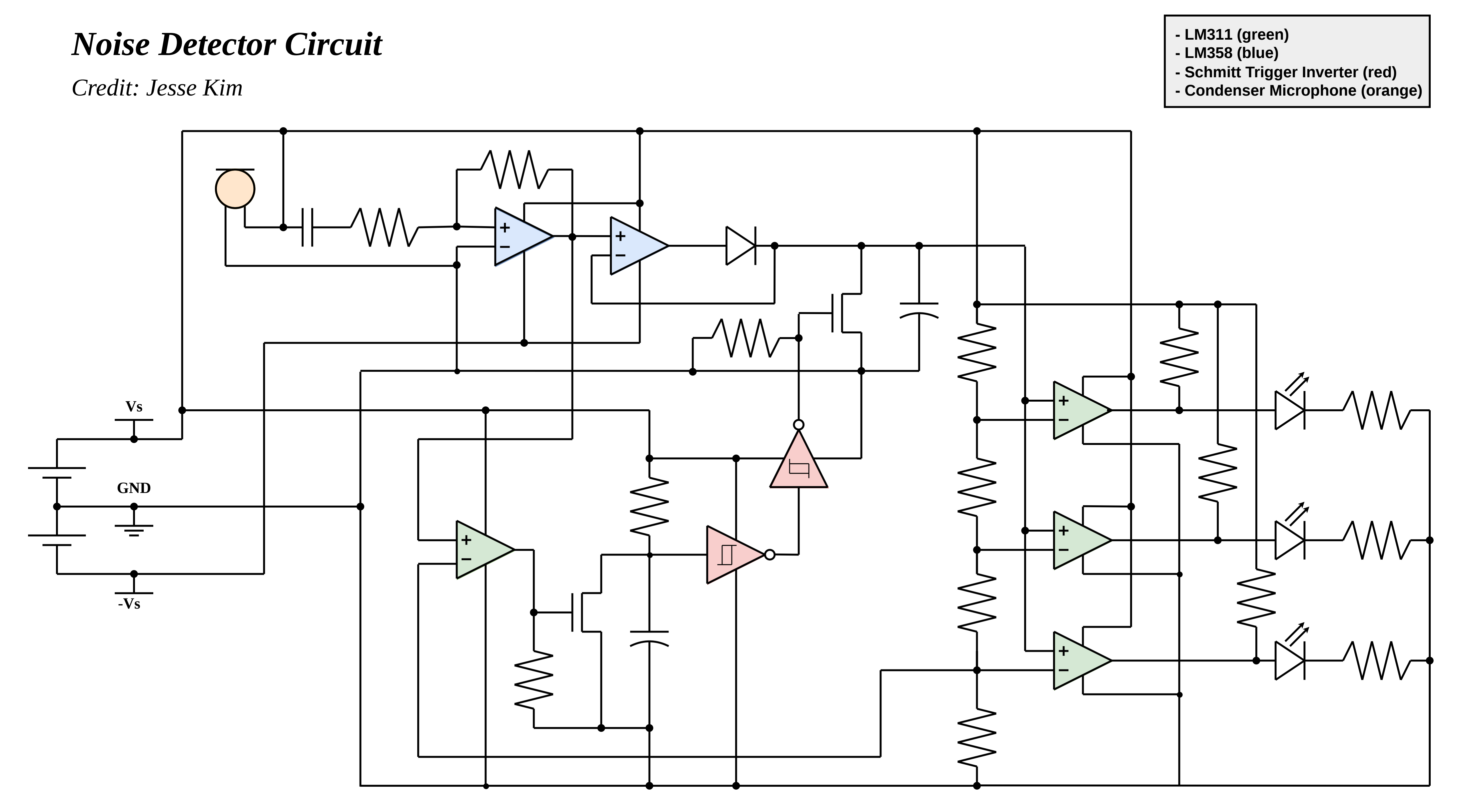
The following documentation is a full explanation and walk through of my Noise Detector PCB, an analog circuit.
The circuit includes an analog signal chain (amplification → peak detection → timed delay → threshold comparison). The components include a condenser microphone, LM358 op-amp, LM311 comparator, and a Schmitt Trigger Inverter.
The design includes an NMOS-switched peak detector, an RC hold time delay circuit to capture audio peak for a set time, and a 3-level voltage comparator network that connects to a 3-level LED volume indicator.
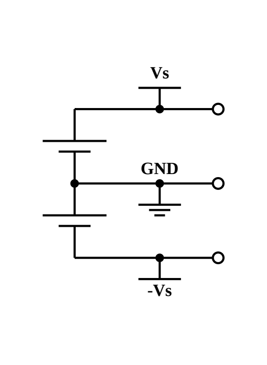
All components in this circuit require a +9V, GND, and -9V. This is created by wiring two 9V batteries in series, creating an 18V difference between the two, and setting the GND to the point inbetween the batteries, creating +9V, 0V, and -9V.
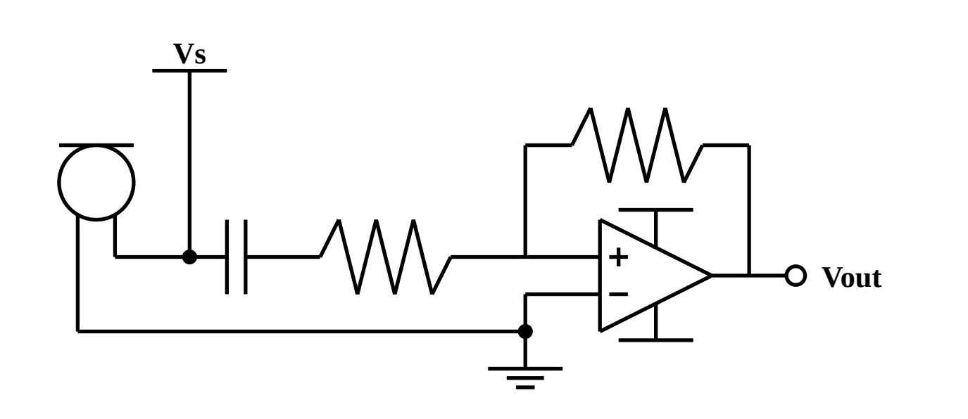
The Condenser Microphone simply converts sound into an electric signal. Sound comes into the microphone and vibrates a diaphragm which creates an induced current. This current is then used to compute a voltage which is the signal we are measuring.
However, for this circuit component the voltage signal amplitude is far too small to read, thus we need to amplify the signal. For this I used an inverting amplifier based on an LM358 OpAmp. The amplification is defined as R2/R1, where R2 is the feedback resistor. This is also known as the gain, in which I chose to use a gain of 100k/47 = 2127.66.
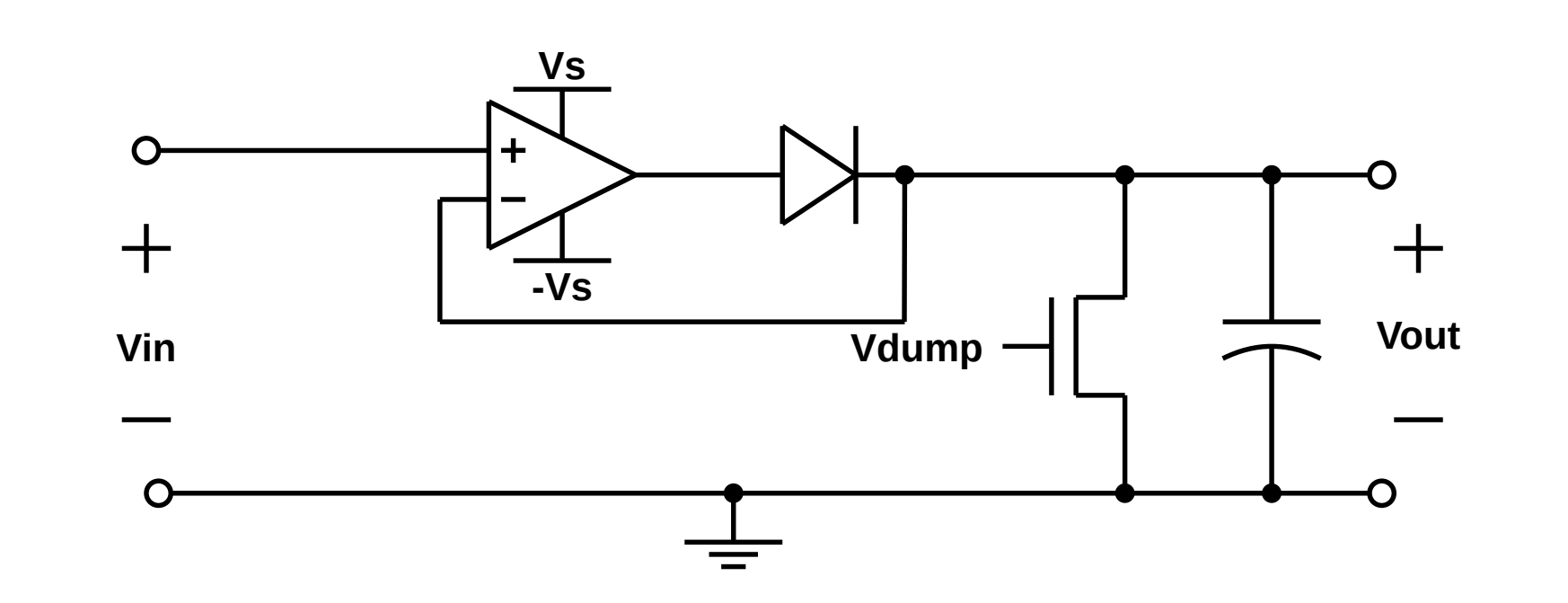
The peak detector module is designed to capture the maximum amplitude of voltage input from a time-varying signal. It does this by using an LM358 OpAmp, which when applying nodal analysis, we can considered the + and - inputs to have the same voltage. In this way connecting the output of the OpAmp to the inverting input creates a voltage follower circuit.
We can extend the design of the voltage follower input by adding a capacitor and diode such that the capacitor charges up to match the maximum voltage amplitude, but has no route to drain on its own. We add an NMOS switch to drain the capacitor, acting as a reset.
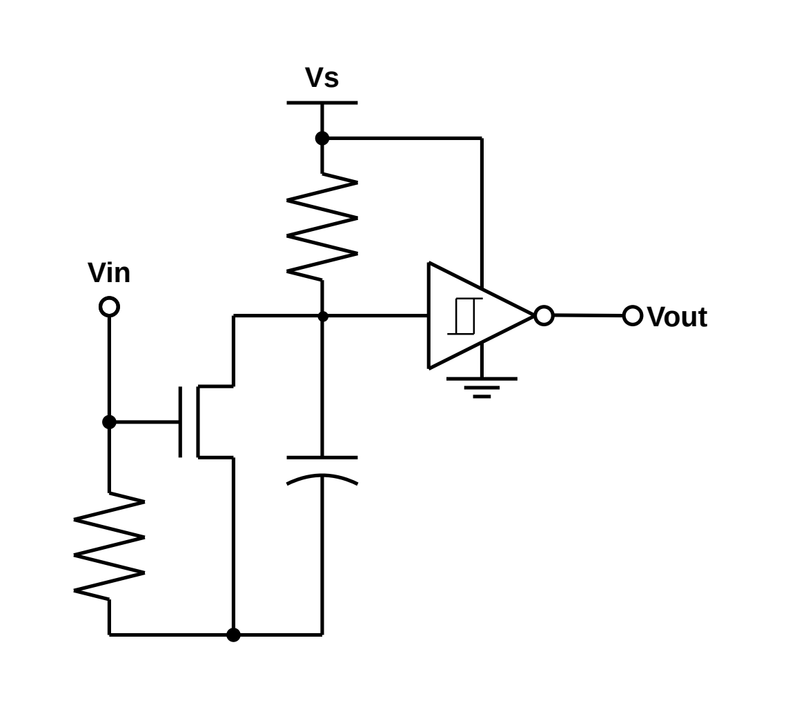
The time delay module provides a controlled delay signal using an RC circuit. This provides our circuit with a fixed time which controls the duration the LEDs remain lit after the initial trigger.
The time delay first uses a comparator that compares the input signal to a voltage threshold. If the signal exceeds that threshold, the time delay begins.
By default the capacitor is fully charged as it has an RC path to Vs, our voltage source. When the threshold is met, an NMOS is switched on, connecting the capacitor to GND, instantly draining it. The capacitor then takes time to recharge, which can be modeled by a commonly known differential equation.
The output of this time delay is fed into a schmitt trigger inverter, which outputs high while the capacitor voltage is below a threshold. I fed this into another inverter, such that the output can reset the peak detector once the RC is above that threshold.
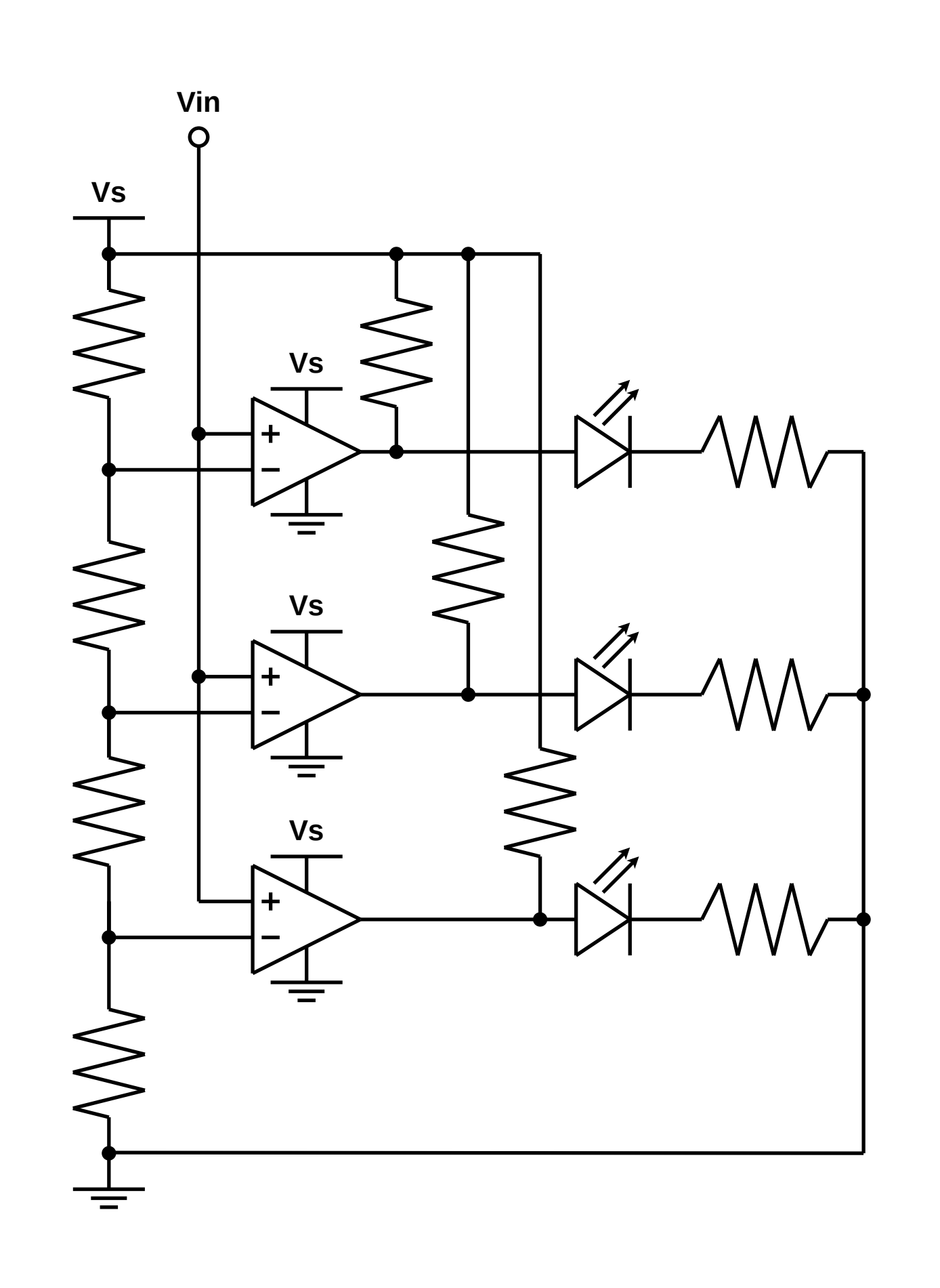
The 3-stage comparator simply uses a resistor/potentiometer network, that acts as a voltage divider, and 3 LM311 high speed comparators to create the module. This compares the output of the peak detector, or our max voltage, and controls a 3-level LED display, indicating volume.
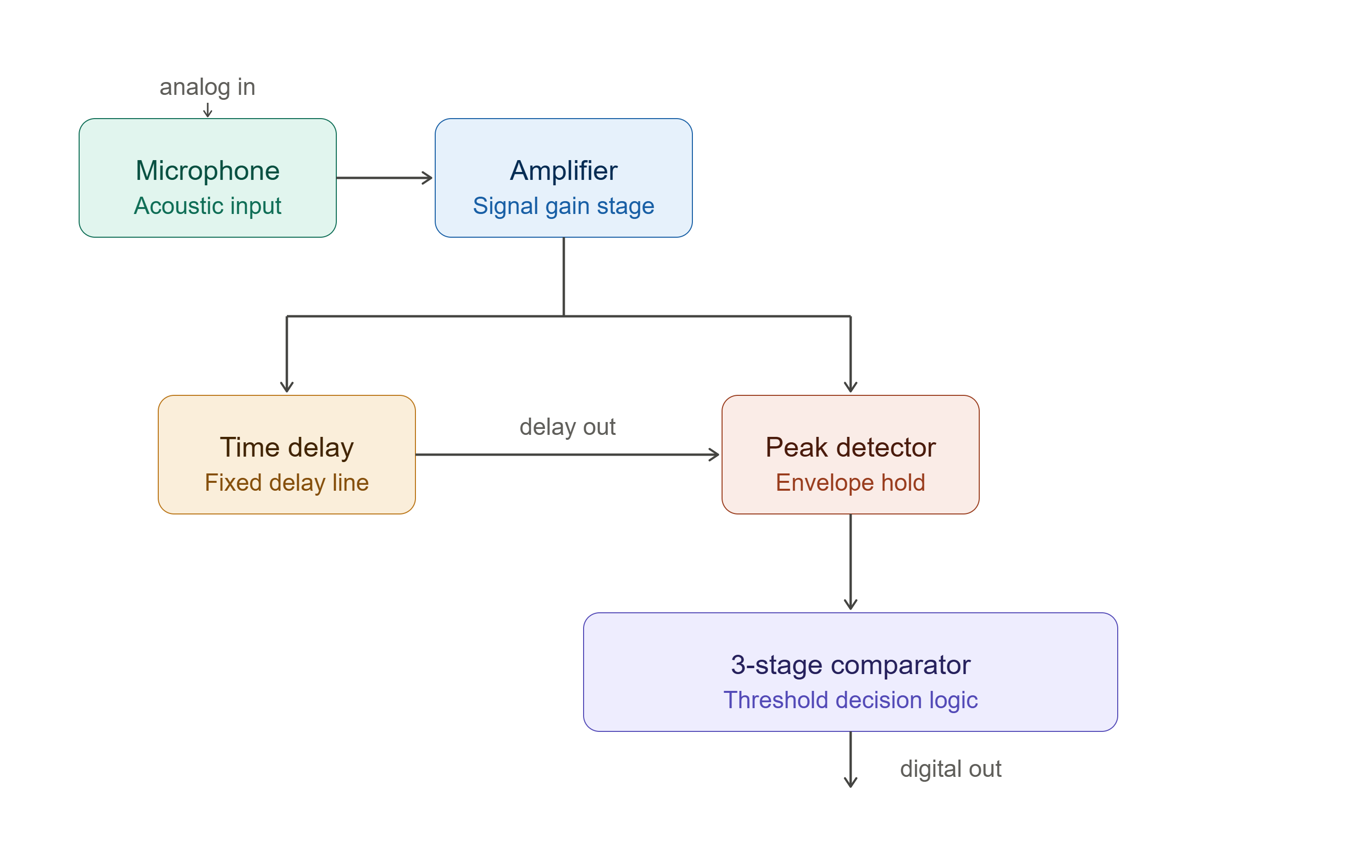
The diagram above describes the analog signal chain used to connect all submodules. The microphone output feeds into the amp, which feeds into the peak detector and time delay. The time delay control the reset of the peak detector and the peak detector output feeds into the comparator.
The final circuit diagram is shown below
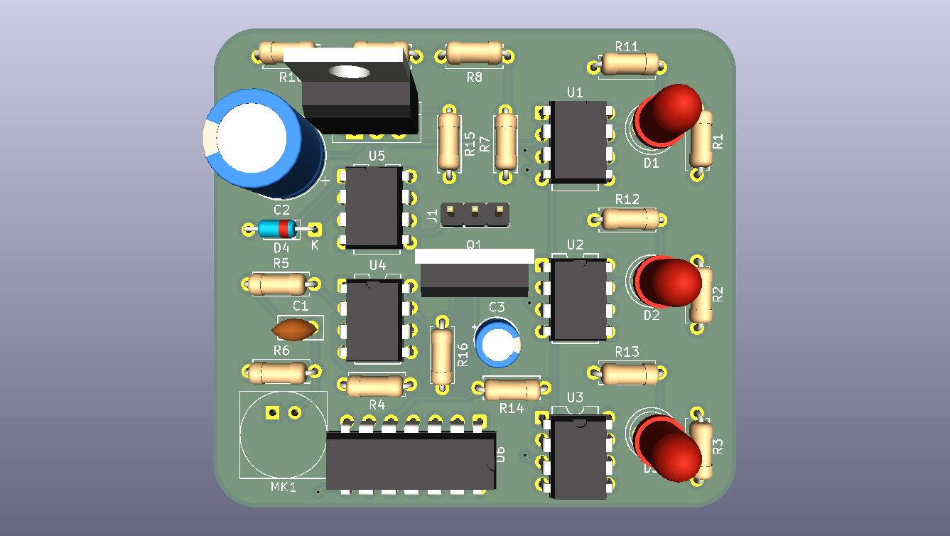
The final circuit was then converted into a PCB design in KiCAD. The design uses a 2-layer PCB, and follows the same circuit design described as above. The PCB passed all design rules checks. The majority of optimizations were in reduce trace length.
| Qty | Value | Footprint | References |
|---|---|---|---|
| 8 | 330Ω | Resistor_THT:R_Axial_DIN0207_L6.3mm_D2.5mm_P7.62mm_Horizontal | R1, R2, R3, R8, R9, R11, R12, R13 |
| 4 | 10kΩ | Resistor_THT:R_Axial_DIN0207_L6.3mm_D2.5mm_P7.62mm_Horizontal | R10, R14, R15, R16 |
| 3 | LED | LED_THT:LED_D5.0mm | D1, D2, D3 |
| 3 | LM311 | Package_DIP:DIP-8_W7.62mm | U1, U2, U3 |
| 2 | 1kΩ | Resistor_THT:R_Axial_DIN0207_L6.3mm_D2.5mm_P7.62mm_Horizontal | R6, R7 |
| 2 | LM358 | Package_DIP:DIP-8_W7.62mm | U4, U5 |
| 2 | Q_NMOS_GDS | Package_TO_SOT_THT:TO-220-3_Vertical | Q1, Q2 |
| 1 | 1000µF | Capacitor_THT:CP_Radial_D10.0mm_P5.00mm | C2 |
| 1 | 100kΩ | Resistor_THT:R_Axial_DIN0207_L6.3mm_D2.5mm_P7.62mm_Horizontal | R4 |
| 1 | 100µF | Capacitor_THT:CP_Radial_D5.0mm_P2.50mm | C3 |
| 1 | 1µF | Capacitor_THT:C_Disc_D5.0mm_W2.5mm_P2.50mm | C1 |
| 1 | 47Ω | Resistor_THT:R_Axial_DIN0207_L6.3mm_D2.5mm_P7.62mm_Horizontal | R5 |
| 1 | 74LS14 | Package_DIP:DIP-14_W7.62mm | U6 |
| 1 | Conn_01x03_Socket | Connector_PinHeader_2.54mm:PinHeader_1x03_P2.54mm_Vertical | J1 |
| 1 | D | Diode_THT:D_DO-35_SOD27_P7.62mm_Horizontal | D4 |
| 1 | Microphone | microphone_footprint:Microphone | MK1 |

MadsRudolph/vinyl-adc
Discrete 3rd-order delta-sigma stereo audio ADC, built from op-amps and logic gates: a four-layer Raspberry Pi HAT made by PCBWay, with KiCad files, SPICE simulations and measurements

CL-YQLM/sitwise
A smart cushion for healthier sitting: occupancy and posture sensing, a sitting timer, haptic and audible feedback, and heating, all on a custom two-layer PCB. UIUC ECE 145 Instructor Award.


lynchaj/duodyne
Duodyne is a hobbyist retrocomputer system designed to run ROMWBW. It is comprised of modules on a system bus

It measures 60 × 55 mm and has 2 copper layers, 1.6 mm thick.
33 parts, built around the LM358, LM311 and 74LS14PC. The full list of its parts is on this page, with links to each part's symbol and footprint where PCBKit's library has them.
From the jtkim00000/noise-detector-pcb repository on GitHub, at the commit this page was made from: the board is src/noise_detector.kicad_pcb and its schematic src/noise_detector.kicad_sch. PCBKit opens the board in the browser, with nothing to install.
Its repository states no licence, so its author keeps all rights: ask jtkim00000 before reusing the design.