2 layers65 × 56 mm

 jstanley0/pico-player8
Music player for Raspberry Pi Pico and a pair of SN76489s
Pico player pcb is an open-source printed circuit board by jstanley0, from the jstanley0/pico-player repository on GitHub, published under the MIT licence. It is a 2-layer board of 57.9 × 65.5 mm with 23 parts on 55 nets, routed with 194 tracks and 0 vias.
Its parts include 8 resistors, 8 diodes, 3 ICs, 2 capacitors and 1 connector. It belongs with the RP2040 boards of this library.
Music player for Raspberry Pi Pico and a pair of SN76489s
firmware (sound.py and music_player.py to your Pico), via rshell cp firmware/* /pyboard or pasting into Thonny, etc.python3 util/convert_midi.py example.mid example.datrshell cp example.dat /pyboard. It is a binary file so pasting it via an IDE isn't going to work.from music_player import MusicPlayer
mp = MusicPlayer()
mp.play_song('example.dat')python3 util/convert_midi.py example.mid -Getting music data into a usable format is tricky. I wrote a script (util/convert_midi.py) that translates note-on and note-off events into a simple binary format that the microcontroller program can parse and play. The primary challenge is that we have only six notes of polyphony to work with, so it works best with simple MIDI files. I suggest opening files in e.g. MuseScore beforehand to identify channels to prioritize (with -p) or exclude (with -x). If no arguments are given, convert_midi.py will prioritize channels in tracks named "melody" or "vocals".
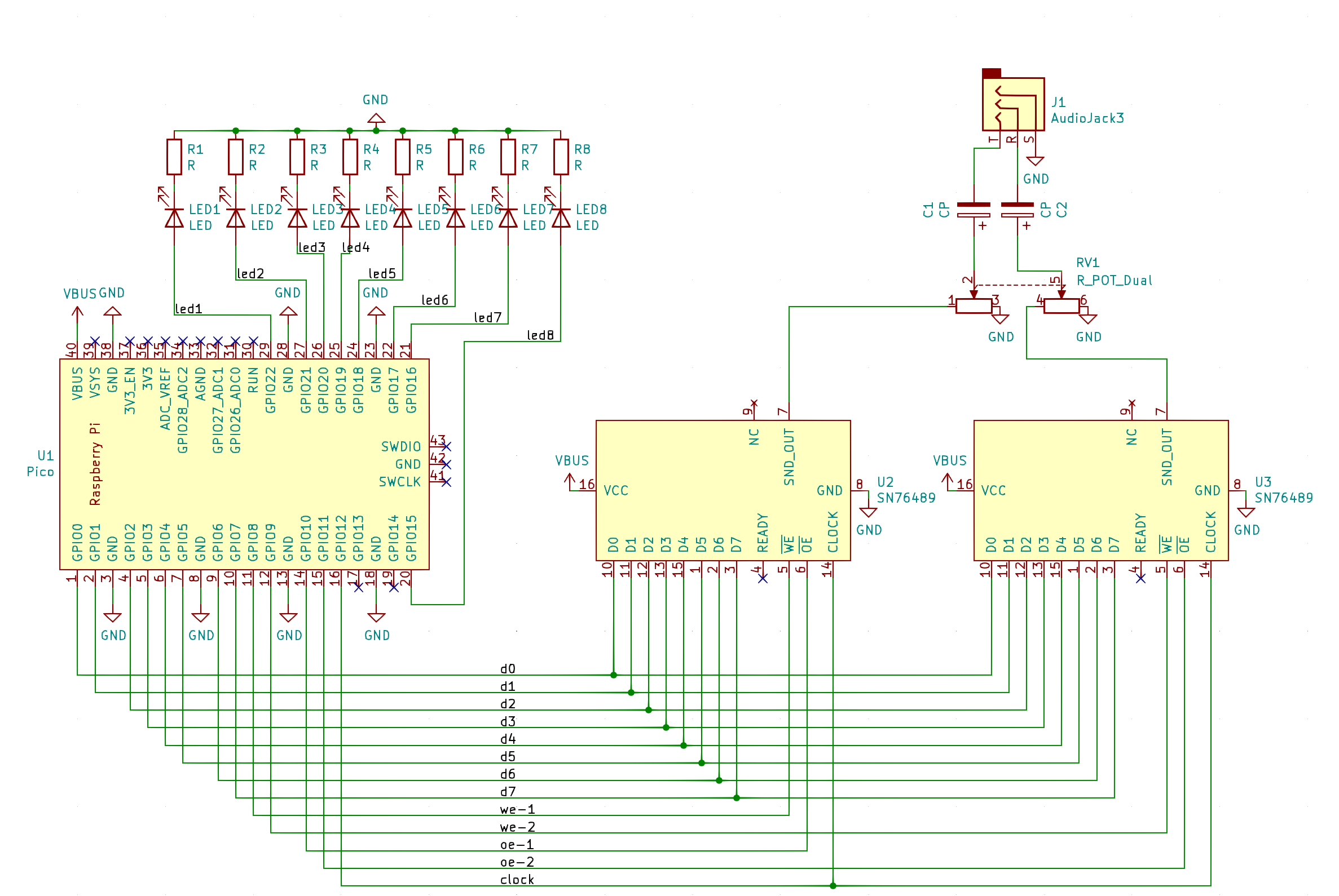
| Qty | Value | Footprint | References |
|---|---|---|---|
| 8 | LED | LED_THT:LED_D5.0mm_Clear | LED1, LED2, LED3, LED4, LED5, LED6, LED7, LED8 |
| 8 | R | Resistor_THT:R_Axial_DIN0309_L9.0mm_D3.2mm_P2.54mm_Vertical | R1, R2, R3, R4, R5, R6, R7, R8 |
| 2 | CP | Capacitor_THT:CP_Radial_D5.0mm_P2.50mm | C1, C2 |
| 2 | SN76489 | Package_DIP:DIP-16_W7.62mm | U2, U3 |
| 1 | AudioJack3 | Connector_Audio:Jack_3.5mm_CUI_SJ1-3533NG_Horizontal | J1 |
| 1 | Pico | RP:RPi_Pico_SMD_TH | U1 |
| 1 | R_POT_Dual | Potentiometer_THT:Potentiometer_Alps_RK09L_Double_Vertical | RV1 |
It measures 57.9 × 65.5 mm and has 2 copper layers, 1.6 mm thick.
23 parts. The full list of its parts is on this page, with links to each part's symbol and footprint where PCBKit's library has them.
From the jstanley0/pico-player repository on GitHub, at the commit this page was made from: the board is pico-player-pcb/pico-player-pcb.kicad_pcb. PCBKit opens the board in the browser, with nothing to install.
Its repository publishes it under the MIT licence: you may reuse it on that licence's terms (keep the author's notice, and for a copyleft licence share your changes alike).

google/mozc-devices
Circuit diagrams and firmware source code for Gboard DIY keyboards


Duet3D/Duet-2-Hardware
The KiCAD source for the Duet 3d printer controller see www.duet3d.com