2 layers100 × 49.9 mm

 jsanpe/c2c-6439
A Composite & S-video to Component transcoder for the OSSC
Composite2rgb is an open-source printed circuit board by jsanpe, from the jsanpe/c2c-64 repository on GitHub, published under the MIT licence. It is a 4-layer board of 50 × 50 mm with 110 parts on 96 nets, routed with 1,140 tracks and 121 vias.
It is built around the ATMEGA328PB-MU, AMS1117-3.3 and BAT54S, with the RCJ-041 among its other parts. Its parts include 39 capacitors, 31 resistors, 8 ICs, 7 diodes and 5 connectors. It belongs with the AVR (ATmega, ATtiny) boards of this library.


A Composite & S-Video to Component Video transcoder to feed older analog signals into your OSSC.
Designed with the C-64 in mind, it also supports composite and s-video signals from other systems, including the N64. A compatibility chart will soon be available in the wiki section of this project.
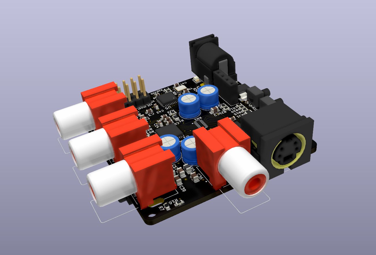
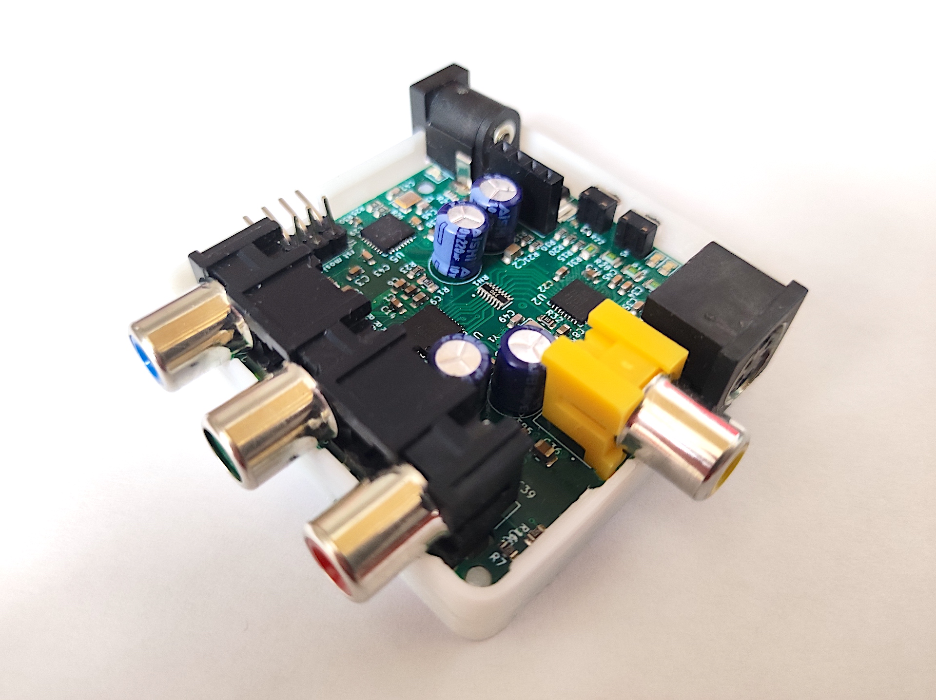
This is an open hardware implementation of a board to convert Composite and S-Video signals into Component video. The component output from C2C-64 can be directly connected to an OSSC, effectively adding compatibility with Composite and S-Video input to this great scaler.
C2C-64 was primarily design as a simple way to connect a C64 to and OSSC. Most of the testing has been done in this platform, and presets have been chosen with it in mind. I have conducted some tests with other machines (N64, SNES, Dreamcast), although not as extensive.
C2C-64 uses a simple pipeline of video decoder and encoder to transform the input composite or S-video signals into component video. What this means in practice is that the analog input is converted to digital format and fed to the encoder to transform it into a different analog signal. This conversion is NOT lossless. However, it enables anyone to conveniently hook such signals directly into the OSSC without tinkering with the internals of their devices.
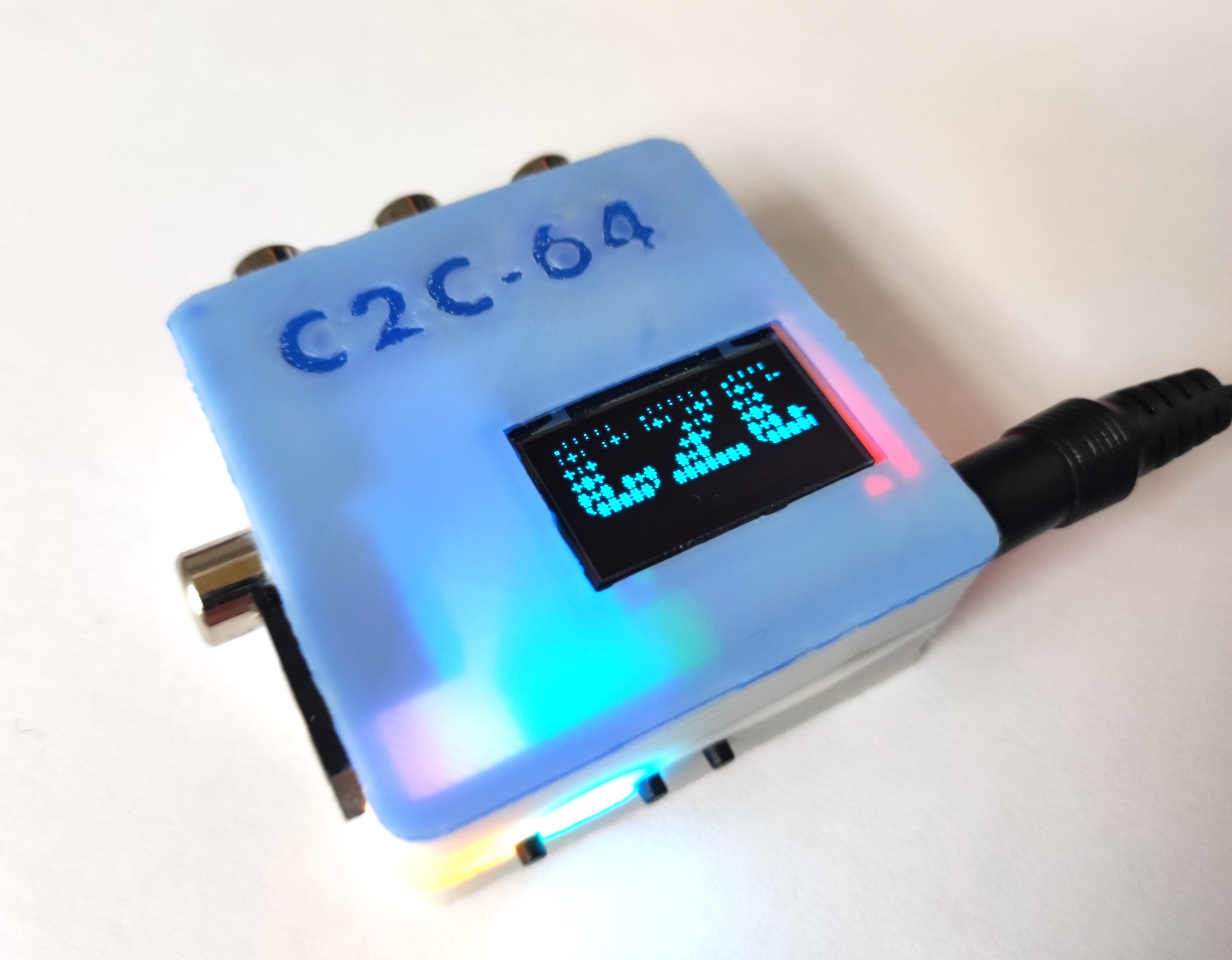
This is an open project, in this repository you will find everything you need in order to build your own C2C-64.
It is important to note that building this requires ninja-grade soldering skills, especially to get those QFN ICs properly connected to the board. Also, sourcing some of the components may be a bit trickier than usual. In particular, the ADV7180 IC is unsupported by Analog anymore and probably AliExpress is the only place where it can be found at this point. There is an ADV7280(A) based version of the C2C (2R) that will be soon released, but the price of this IC is way more expensive.
I am in the process of building a first batch of 35 boards (version 1R3) that I will be selling to anyone interested in supporting the project. Reach me directly if you are interested at com2com64@gmail.com. I will be compiling a list and start shipping them on a first come first served basis.
You can also support the project by donating through my KoFi page

In terms of functionality, C2C-64 provides a similar experience to the commercial product Koryuu. However, there are notable differences between C2C-64 and Koryuu:
One important improvement of C2C-64 over Koryuu is the inclusion of powerful interfacing options. The board provides three main ways of allowing user interaction:
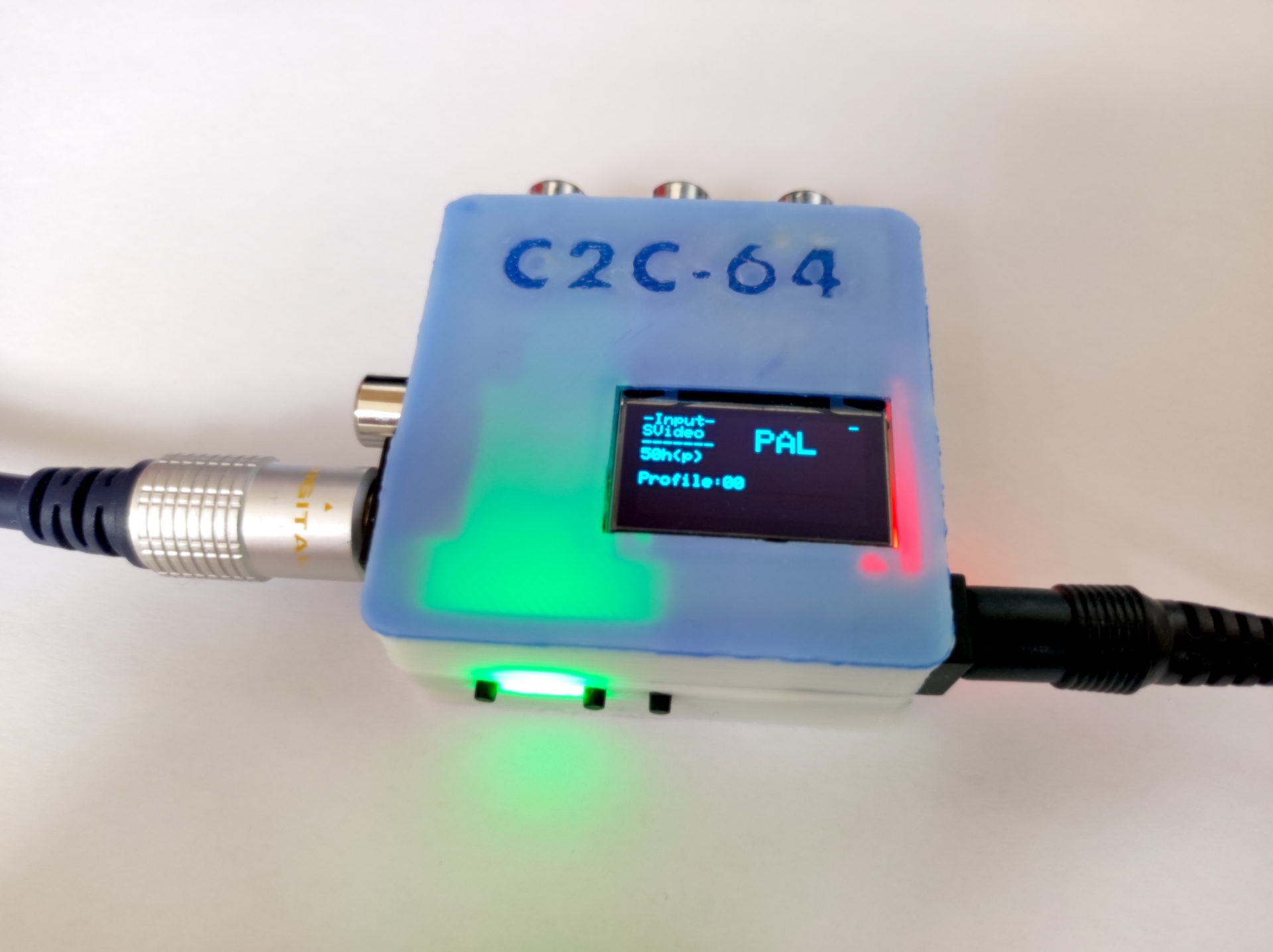
There are also 4 leds that are used to show important signals about the operation of the board
This project is still WiP. The repository contains only a beta version of the firmware required to run the board. Keep checking this page for updates.
| Qty | Value | Footprint | References |
|---|---|---|---|
| 10 | 10uF | Capacitor_SMD:C_0603_1608Metric | C4, C8, C9, C14, C16, C19, C22, C24, C26, C31 |
| 8 | 4k7 | Resistor_SMD:R_0603_1608Metric | R2, R7, R10, R15, R16, R19, R20, R21 |
| 7 | 100nF | Capacitor_SMD:C_0603_1608Metric | C3, C33, C34, C35, C38, C43, C45 |
| 6 | Ferrite_Bead | Inductor_SMD:L_0805_2012Metric | FB1, FB2, FB3, FB4, FB5, FB6 |
| 4 | 220uF | Capacitor_THT:C_Radial_D6.3mm_H5.0mm_P2.50mm | C37, C40, C41, C42 |
| 4 | 22u | Capacitor_SMD:C_0805_2012Metric_Pad1.18x1.45mm_HandSolder | C2, C7, C12, C17 |
| 4 | 30pF | Capacitor_SMD:C_0603_1608Metric | C46, C47, C49, C51 |
| 4 | MountingHole | MountingHole:MountingHole_2.5mm | H1, H2, H3, H4 |
| 4 | SW_Push | Button_Switch_THT:mini-btn | SW1, SW2, SW4, SW5 |
| 3 | 100nF | Capacitor_SMD:C_0402_1005Metric | C28, C29, C44 |
| 3 | 10k | Resistor_SMD:R_0402_1005Metric | R22, R29, R30 |
| 3 | 36 | Resistor_SMD:R_0805_2012Metric | R14, R17, R28 |
| 3 | 39 | Resistor_SMD:R_0805_2012Metric | R12, R18, R31 |
| 3 | 75 | Resistor_SMD:R_0805_2012Metric | R4, R5, R6 |
| 3 | BAT54S | Package_TO_SOT_SMD:SOT-23 | D1, D2, D3 |
| 2 | 220 | Resistor_SMD:R_0603_1608Metric | R26, R27 |
| 2 | 22u | Capacitor_SMD:C_0805_2012Metric | C36, C39 |
| 2 | 33 | Resistor_SMD:R_0805_2012Metric | R33, R34 |
| 2 | TLV70018_SOT23-5 | Package_TO_SOT_SMD:SOT-23-5 | U3, U6 |
| 1 | 1.5A | Fuse:Fuse_0402_1005Metric | F1 |
| 1 | 1.69K | Resistor_SMD:R_0603_1608Metric | R9 |
| 1 | 10k | Resistor_SMD:R_0603_1608Metric | R23 |
| 1 | 10n | Capacitor_SMD:C_0603_1608Metric | C50 |
| 1 | 120 | Resistor_SMD:R_0603_1608Metric | R25 |
| 1 | 12n | Capacitor_SMD:C_0603_1608Metric | C1 |
| 1 | 150n | Capacitor_SMD:C_0603_1608Metric | C6 |
| 1 | 169 | Resistor_SMD:R_0805_2012Metric | R1 |
| 1 | 16Mhz | Crystal:Crystal_C38-LF_D3.0mm_L8.0mm_Vertical | Y2 |
| 1 | 16Mhz | Crystal:Crystal_SMD_3225-4Pin_3.2x2.5mm | Y3 |
| 1 | 1M | Resistor_SMD:R_0603_1608Metric | R32 |
| 1 | 2.2n | Capacitor_SMD:C_0603_1608Metric | C11 |
| 1 | 28.63 | Crystal:Crystal_C38-LF_D3.0mm_L8.0mm_Vertical | Y6 |
| 1 | 33 | RCJ-041:RESCAXE50P380X160X55-16N | RN1 |
| 1 | 330 | Resistor_SMD:R_0603_1608Metric | R24 |
| 1 | 3xCUI-RCJ | RCJ-041:3xCUI_RCJ-041 | U8 |
| 1 | 3xRCA_CONN | RCJ-041:TRRS-PJ-320A | U7 |
| 1 | 510 | Resistor_SMD:R_0805_2012Metric | R3 |
| 1 | 82n | Capacitor_SMD:C_0603_1608Metric | C30 |
| 1 | ADV7180-32LFCSP | Package_CSP:LFCSP-32-1EP_5x5mm_P0.5mm_EP3.1x3.1mm_ThermalVias | U2 |
| 1 | ADV7393-Video | Package_DFN_QFN:QFN-40-1EP_6x6mm_P0.5mm_EP4.6x4.6mm_ThermalVias | U1 |
| 1 | AMS1117-3.3 | Package_TO_SOT_SMD:SOT-223-3_TabPin2 | U4 |
| 1 | ATmega328PB-MU | Package_DFN_QFN:QFN-32-1EP_5x5mm_P0.5mm_EP3.1x3.1mm | U5 |
| 1 | Conn_01x04_Female | Connector_PinSocket_2.54mm:PinSocket_1x04_P2.54mm_Vertical | J8 |
| 1 | Conn_02x04_Top_Bottom | Connector_PinHeader_2.54mm:PinHeader_2x04_P2.54mm_Vertical | J1 |
| 1 | Crystal_GND24_Small | Crystal:Crystal_SMD_3225-4Pin_3.2x2.5mm | Y1 |
| 1 | LED_B | LED_SMD:LED_0805_2012Metric | D5 |
| 1 | LED_G | LED_SMD:LED_0805_2012Metric | D6 |
| 1 | LED_R | LED_SMD:LED_0805_2012Metric | D4 |
| 1 | LED_Y | LED_SMD:LED_0805_2012Metric | D7 |
| 1 | Mini-DIN-4 | RCJ-041:CUI_MD-50S | J4 |
| 1 | Power | Connector_BarrelJack:BarrelJack_Horizontal | J6 |
| 1 | RCJ-041 | RCJ-041:CUI_RCJ-041 | J10 |
It measures 50 × 50 mm and has 4 copper layers, 1.6 mm thick.
110 parts, built around the ATMEGA328PB-MU, AMS1117-3.3, BAT54S and RCJ-041. The full list of its parts is on this page, with links to each part's symbol and footprint where PCBKit's library has them.
From the jsanpe/c2c-64 repository on GitHub, at the commit this page was made from: the board is hardware/1R/1R3/composite2rgb.kicad_pcb and its schematic hardware/1R/1R3/Decoder.kicad_sch. PCBKit opens the board in the browser, with nothing to install.
Its repository publishes it under the MIT licence: you may reuse it on that licence's terms (keep the author's notice, and for a copyleft licence share your changes alike).


miakizz/Videoscope
Board for viewing composite video (PAL, NTSC, or SECAM) on an oscilliscope This is a layout of this circuit by W2AEW


butterstick-fpga/butterstick-hardware
Basic ECP5 based GigE to SYZYGY interface.


0101shift/Project_OAK
All design files, source code, and documentation for Project OAK, a digital watch inspired by mechanical complications.
