2 layers99.1 × 99.1 mm

 JordanAceto/angelo_modular2
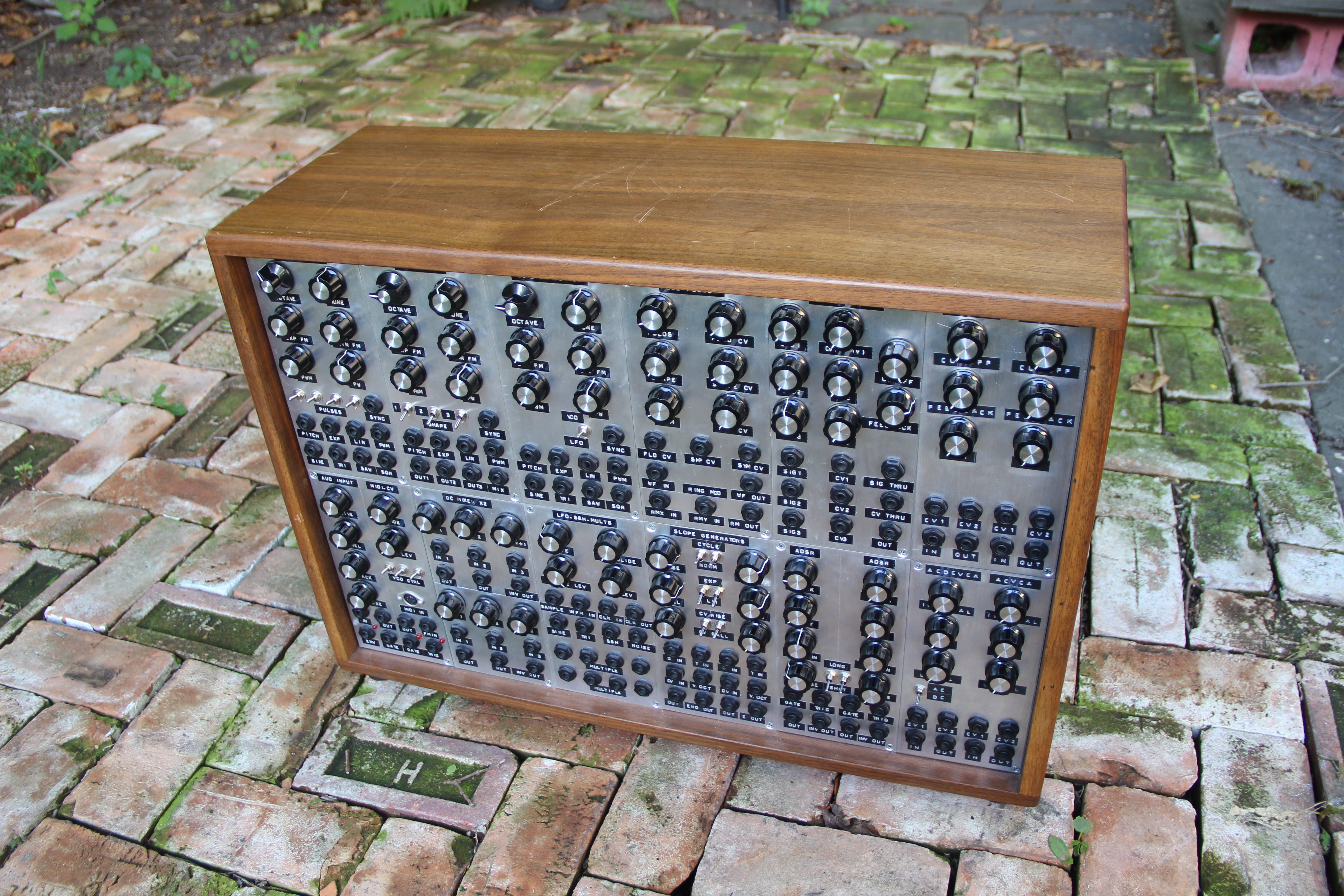
modular analog synthesizer for a.p.
Modulation source is an open-source printed circuit board by JordanAceto, from the JordanAceto/angelo_modular repository on GitHub, published under the CC-BY-4.0 licence. It is a 2-layer board of 99.1 × 68.6 mm with 73 parts on 52 nets, routed with 383 tracks and 47 vias.
It is built around the TL072, LM13700M and BC550, with the BC560 and BF245A among its other parts. Its parts include 34 resistors, 16 capacitors, 6 transistors, 4 ICs and 3 diodes.


/user_manuals/ directory. This directory also contains a document outlining any pcb kludges or changes to the current system./pcb_docs/ directoryA very brief README outlining the basics of the pcb
/construction_docs/ subdirectory which contains:
/kicad_docs/ subdirectory which contains the files needed to edit the schematic and pcb layout with kicad
/pics/ subdirectory which contains a few rendered pictures of the pcb for reference
| Qty | Value | Footprint | References |
|---|---|---|---|
| 9 | 100nF | Capacitor_SMD:C_0805_2012Metric_Pad1.15x1.40mm_HandSolder | C8, C9, C10, C11, C12, C13, C14, C15, C16 |
| 5 | 15k | Resistor_SMD:R_0805_2012Metric_Pad1.15x1.40mm_HandSolder | R13, R14, R17, R28, R29 |
| 5 | 1k | Resistor_SMD:R_0805_2012Metric_Pad1.15x1.40mm_HandSolder | R16, R18, R31, R32, R33 |
| 4 | 33k | Resistor_SMD:R_0805_2012Metric_Pad1.15x1.40mm_HandSolder | R3, R7, R11, R12 |
| 3 | 100k | Potentiometer_THT:Potentiometer_Alpha_RD901F-40-00D_Single_Vertical | RV1, RV2, RV3 |
| 3 | 10k | Resistor_SMD:R_0805_2012Metric_Pad1.15x1.40mm_HandSolder | R10, R21, R25 |
| 3 | 1N4148 | Diode_THT:D_DO-35_SOD27_P7.62mm_Horizontal | D1, D2, D3 |
| 3 | 2k | Resistor_SMD:R_0805_2012Metric_Pad1.15x1.40mm_HandSolder | R6, R8, R9 |
| 3 | BC550 | Package_TO_SOT_THT:TO-92_Inline | Q4, Q5, Q6 |
| 3 | TL072 | Package_DIP:DIP-8_W7.62mm | U2, U3, U4 |
| 2 | 100k | Resistor_SMD:R_0805_2012Metric_Pad1.15x1.40mm_HandSolder | R1, R5 |
| 2 | 10nF | Capacitor_SMD:C_0805_2012Metric_Pad1.15x1.40mm_HandSolder | C1, C2 |
| 2 | 10uF | Capacitor_THT:CP_Radial_D6.3mm_P2.50mm | C6, C7 |
| 2 | 2k2 | Resistor_SMD:R_0805_2012Metric_Pad1.15x1.40mm_HandSolder | R20, R27 |
| 2 | 50k | Potentiometer_THT:Potentiometer_Bourns_3296W_Vertical | RV4, RV5 |
| 2 | BC560 | Package_TO_SOT_THT:TO-92_Inline | Q1, Q2 |
| 1 | 10M | Resistor_SMD:R_0805_2012Metric_Pad1.15x1.40mm_HandSolder | R30 |
| 1 | 150k | Resistor_SMD:R_0805_2012Metric_Pad1.15x1.40mm_HandSolder | R24 |
| 1 | 18k | Resistor_SMD:R_0805_2012Metric_Pad1.15x1.40mm_HandSolder | R23 |
| 1 | 1M | Resistor_SMD:R_0805_2012Metric_Pad1.15x1.40mm_HandSolder | R26 |
| 1 | 1MA | Potentiometer_THT:Potentiometer_Alpha_RD901F-40-00D_Single_Vertical | RV7 |
| 1 | 1k | Potentiometer_THT:Potentiometer_Bourns_3296W_Vertical | RV6 |
| 1 | 1uF | Capacitor_THT:CP_Radial_D6.3mm_P2.50mm | C5 |
| 1 | 200k | Resistor_SMD:R_0805_2012Metric_Pad1.15x1.40mm_HandSolder | R2 |
| 1 | 220k | Resistor_SMD:R_0805_2012Metric_Pad1.15x1.40mm_HandSolder | R34 |
| 1 | 220nF | Capacitor_SMD:C_0805_2012Metric_Pad1.15x1.40mm_HandSolder | C3 |
| 1 | 270k | Resistor_SMD:R_0805_2012Metric_Pad1.15x1.40mm_HandSolder | R4 |
| 1 | 27k | Resistor_SMD:R_0805_2012Metric_Pad1.15x1.40mm_HandSolder | R19 |
| 1 | 390 | Resistor_SMD:R_0805_2012Metric_Pad1.15x1.40mm_HandSolder | R22 |
| 1 | 47uF | Capacitor_THT:CP_Radial_D6.3mm_P2.50mm | C4 |
| 1 | 51k | Resistor_SMD:R_0805_2012Metric_Pad1.15x1.40mm_HandSolder | R15 |
| 1 | BF245A | Package_TO_SOT_THT:TO-92_Inline | Q3 |
| 1 | Conn_01x04 | Connector_PinHeader_2.54mm:PinHeader_1x04_P2.54mm_Vertical | inputs1 |
| 1 | Conn_01x06 | Connector_PinHeader_2.54mm:PinHeader_1x06_P2.54mm_Vertical | outputs1 |
| 1 | LM13700 | Package_DIP:DIP-16_W7.62mm | U1 |
| 1 | power_in | Connector_PinHeader_2.54mm:PinHeader_2x05_P2.54mm_Vertical | J1 |
It measures 99.1 × 68.6 mm and has 2 copper layers, 1.6 mm thick.
73 parts, built around the TL072, LM13700M, BC550 and BC560. The full list of its parts is on this page, with links to each part's symbol and footprint where PCBKit's library has them.
From the JordanAceto/angelo_modular repository on GitHub, at the commit this page was made from: the board is pcb_docs/modulation_source/kicad_docs/modulation_source.kicad_pcb. PCBKit opens the board in the browser, with nothing to install.
Its repository publishes it under the CC-BY-4.0 licence: you may reuse it on that licence's terms (keep the author's notice, and for a copyleft licence share your changes alike).


JordanAceto/angelo_modular
modular analog synthesizer for a.p.

aether-machine/State-Space-Computer
Schematics and PCBs for Aether Machine open source state space modelling computer and sound synthesizer.


JordanAceto/modulation_source
Eurorack compatible pcb with sine/square VCLFO, white and pink noise, and sample & hold


bubbajfett/kicad-guitar-pedals
collection of guitar pedal PCB layouts in kicad

J-K-Kowalski/PCSK225-Antenna
2026-08-02 - recalculate resistors value 2024-10-08 - fixed GND symbol 2024-06-18 - new version of Ferrite Holder

Acramonics/transmanium
My PCB layout for Jake Rothman's Transmanium pedal from PE November 2025

Chrismettal/PedalDev
Complete audio effect stompbox ecosystem and collection of designs