2 layers80.9 × 108.2 mm
 JordanAceto/modulation_source6
Eurorack compatible pcb with sine/square VCLFO, white and pink noise, and sample & hold
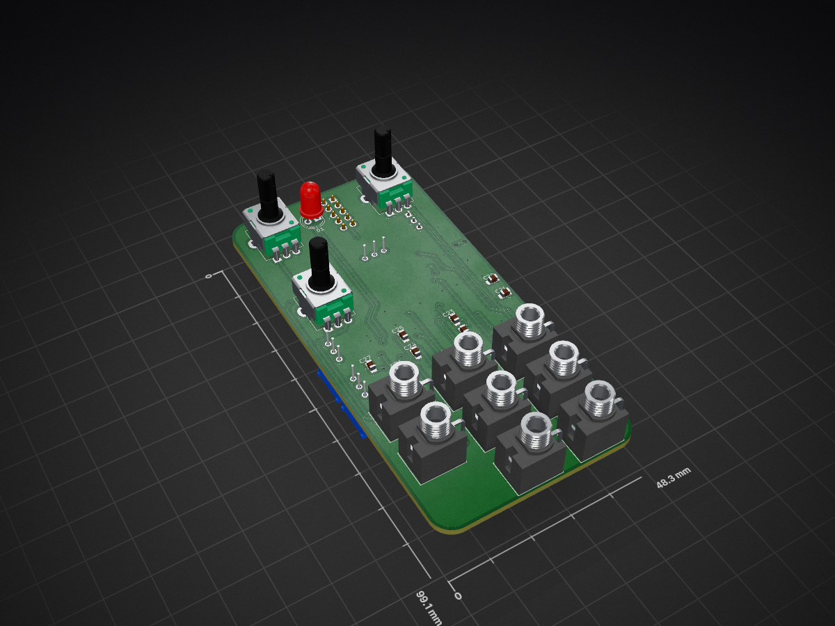
Modulation source is an open-source printed circuit board by JordanAceto, from the JordanAceto/modulation_source repository on GitHub. It is a 2-layer board of 48.3 × 99.1 mm with 95 parts on 66 nets, routed with 465 tracks and 68 vias.
It is built around the TL072, LM13700M and PJ301M-12, with the 1N4148W, MMBT3904 and MMBT3906 among its other parts. Its parts include 40 resistors, 26 capacitors, 9 connectors, 5 ICs and 5 transistors.


| Task | Status |
|---|---|
| Schematic capture | ☑ |
| PCB layout | ☑ |
| Test build | ☑ |
| Safe to order boards | ☑ |
| Qty | Value | Footprint | References |
|---|---|---|---|
| 12 | 100nF | Capacitor_SMD:C_0805_2012Metric_Pad1.15x1.40mm_HandSolder | C4, C14, C18, C19, C20, C21, C22, C23, C24, C25, C26, C27 |
| 8 | PJ301M-12 | modulation_source:PJ301M-12 | J1, J2, J3, J4, J5, J6, J7, J8 |
| 5 | 10k | Resistor_SMD:R_0805_2012Metric_Pad1.15x1.40mm_HandSolder | R9, R14, R17, R30, R32 |
| 5 | 1k | Resistor_SMD:R_0805_2012Metric_Pad1.15x1.40mm_HandSolder | R21, R26, R27, R39, R40 |
| 5 | 33k | Resistor_SMD:R_0805_2012Metric_Pad1.15x1.40mm_HandSolder | R7, R23, R24, R25, R33 |
| 4 | TL072 | Package_SO:SOIC-8_3.9x4.9mm_P1.27mm | U2, U3, U4, U5 |
| 3 | 100k | Resistor_SMD:R_0805_2012Metric_Pad1.15x1.40mm_HandSolder | R1, R3, R34 |
| 3 | 10nF | Capacitor_SMD:C_0805_2012Metric_Pad1.15x1.40mm_HandSolder | C2, C3, C12 |
| 3 | 10uF | Capacitor_SMD:C_0805_2012Metric_Pad1.15x1.40mm_HandSolder | C6, C16, C17 |
| 3 | 1N4148W | Diode_SMD:D_SOD-123 | D2, D3, D4 |
| 3 | 2k2 | Resistor_SMD:R_0805_2012Metric_Pad1.15x1.40mm_HandSolder | R8, R13, R18 |
| 2 | 100k | Potentiometer_THT:Potentiometer_Alpha_RD901F-40-00D_Single_Vertical | RV1, RV2 |
| 2 | 12k | Resistor_SMD:R_0805_2012Metric_Pad1.15x1.40mm_HandSolder | R10, R11 |
| 2 | 15k | Resistor_SMD:R_0805_2012Metric_Pad1.15x1.40mm_HandSolder | R19, R20 |
| 2 | 1M | Resistor_SMD:R_0805_2012Metric_Pad1.15x1.40mm_HandSolder | R29, R36 |
| 2 | 2k | Resistor_SMD:R_0805_2012Metric_Pad1.15x1.40mm_HandSolder | R5, R6 |
| 2 | 3k3 | Resistor_SMD:R_0805_2012Metric_Pad1.15x1.40mm_HandSolder | R22, R31 |
| 2 | 50k | Potentiometer_THT:Potentiometer_Bourns_3296W_Vertical | RV3, RV4 |
| 2 | MMBT3904 | Package_TO_SOT_SMD:SOT-23_Handsoldering | Q3, Q4 |
| 2 | MMBT3906 | Package_TO_SOT_SMD:SOT-23_Handsoldering | Q1, Q2 |
| 1 | 100pF | Capacitor_SMD:C_0805_2012Metric_Pad1.15x1.40mm_HandSolder | C8 |
| 1 | 120k | Resistor_SMD:R_0805_2012Metric_Pad1.15x1.40mm_HandSolder | R4 |
| 1 | 150k | Resistor_SMD:R_0805_2012Metric_Pad1.15x1.40mm_HandSolder | R28 |
| 1 | 18k | Resistor_SMD:R_0805_2012Metric_Pad1.15x1.40mm_HandSolder | R16 |
| 1 | 1M8 | Resistor_SMD:R_0805_2012Metric_Pad1.15x1.40mm_HandSolder | R37 |
| 1 | 1MA | Potentiometer_THT:Potentiometer_Alpha_RD901F-40-00D_Single_Vertical | RV5 |
| 1 | 1nF | Capacitor_SMD:C_0805_2012Metric_Pad1.15x1.40mm_HandSolder | C10 |
| 1 | 1uF | Capacitor_SMD:C_0805_2012Metric_Pad1.15x1.40mm_HandSolder | C7 |
| 1 | 220k | Resistor_SMD:R_0805_2012Metric_Pad1.15x1.40mm_HandSolder | R2 |
| 1 | 27k | Resistor_SMD:R_0805_2012Metric_Pad1.15x1.40mm_HandSolder | R12 |
| 1 | 330k | Resistor_SMD:R_0805_2012Metric_Pad1.15x1.40mm_HandSolder | R35 |
| 1 | 330pF | Capacitor_SMD:C_0805_2012Metric_Pad1.15x1.40mm_HandSolder | C9 |
| 1 | 33nF | Capacitor_SMD:C_0805_2012Metric_Pad1.15x1.40mm_HandSolder | C13 |
| 1 | 390 | Resistor_SMD:R_0805_2012Metric_Pad1.15x1.40mm_HandSolder | R15 |
| 1 | 3n3 | Capacitor_SMD:C_0805_2012Metric_Pad1.15x1.40mm_HandSolder | C11 |
| 1 | 470nF | Capacitor_THT:C_Rect_L7.0mm_W3.5mm_P5.00mm | C1 |
| 1 | 47uF | Capacitor_SMD:C_0805_2012Metric_Pad1.15x1.40mm_HandSolder | C5 |
| 1 | 4M7 | Resistor_SMD:R_0805_2012Metric_Pad1.15x1.40mm_HandSolder | R38 |
| 1 | 5k | Potentiometer_THT:Potentiometer_Bourns_3296W_Vertical | RV6 |
| 1 | BC550 | Package_TO_SOT_THT:TO-92_Inline_Wide | Q5 |
| 1 | LM13700 | Package_SO:SOIC-16_3.9x9.9mm_P1.27mm | U1 |
| 1 | power_in | Connector_PinHeader_2.54mm:PinHeader_2x05_P2.54mm_Vertical | J9 |
| 1 | red_green_LED | LED_THT:LED_D5.0mm | D1 |
It measures 48.3 × 99.1 mm and has 2 copper layers, 1.6 mm thick.
95 parts, built around the TL072, LM13700M, PJ301M-12 and 1N4148W. The full list of its parts is on this page, with links to each part's symbol and footprint where PCBKit's library has them.
From the JordanAceto/modulation_source repository on GitHub, at the commit this page was made from: the board is main_pcb/kicad_docs/modulation_source.kicad_pcb. PCBKit opens the board in the browser, with nothing to install.
Its repository states no licence, so its author keeps all rights: ask JordanAceto before reusing the design.

Thorinair/Avalon-Harmonics
A collection of Avalon Harmonics branded synthesizer modules.


punkfab/pcb-corpus
235 real KiCad boards from open-source hardware repositories, prepared as a placement and routing benchmark

mzuelch/CATs-Eurosynth
Analog Synth Eurorack Modules


