6 layers245.6 × 153.7 mm

 jonthomasson/retro15
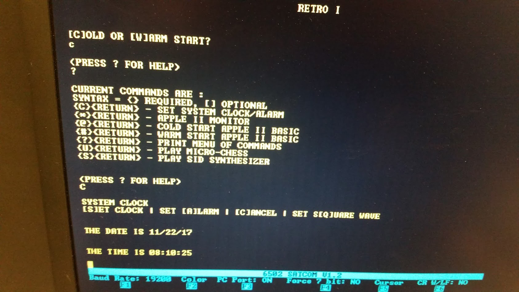
A 6502 computer inspired by the Apple 1.
6502Computer is an open-source printed circuit board by jonthomasson, from the jonthomasson/retro1 repository on GitHub. It is a 2-layer board of 230.5 × 134.6 mm with 136 parts on 203 nets, routed with 3,336 tracks and 239 vias.
It is built around the MIC29150-3.3WT, MIC29150-5.0WT and MIC29152WT, with the JUMPER3 and 2N2222A among its other parts. Its parts include 43 capacitors, 24 resistors, 21 connectors, 16 ICs and 4 switches. It belongs with the retro computing and games boards of this library.


A 6502 computer inspired by the Apple 1.
After completing the Nand2Tetris course, I had a hankering for creating an actual working computer that I could solder together and program. I took on this challenge mostly for the learning experience. My goals were to get some more experience with digital logic, learn assembly programming, and gain more familiarity with Kicad. I chose the 6502 processor since it was really well documented, fairly simple in design, and had a slew of projects I could glean information off of. These projects included The 6502 Home Computer found at grappendorf.net. This project, built by Dirk Grappendorf, was truly amazing. The level of detail he went to for the build logs and the design of the case and other areas of the computer were just incredible. This project greatly aided me in setting up the SID chip, and interfacing it with the 65C02. Another great project that helped me in getting my address decoding circuits up and running was Grant Searle's Simple 6502 Computer. Grant is a legend in my eyes. He seems to be a master at both hardware and software design. Along the path of learning, I also built an L-Star, designed by a true genius, Jac Goudsmit. Jac had the clever idea to interface the 6502 cpu with a Parallax Propeller microcontroller. The Propeller would take care of the address decoding, memory, and i/o. The L-Star works phenomenally well, and I had a blast just playing around with the Woz monitor and Apple 1 BASIC. It was the L-Star project that gave me the idea of using the Propeller to connect to the 65C02 by way of the ACIA UART. From there the Propeller outputs text onto a VGA monitor. The PS/2 Keyboard and the SD Card also interface with the Propeller chip. If you're interested in looking at some of my build/learning log, I attached it as a pdf to this project. Last but not least, the entire 6502.org forum provided a wealth of knowledge and many useful links in getting started with designing a 6502 computer.
Although this was my first computer design, I had a few design rules that I wanted to try and stick to. The first rule was that for the sake of diy, simplicity, and nostalgia for 8 bit computers of the 80s, I wanted to use mostly all through hole components. This led to a larger board size, but it would help make the finished board easier to test and modify later. I also stuck with a green solder mask, and red power led to complete the nostalgic motif. My second goal was to try and create a flexible design, that wasn't just a computer, but could also work as a learning platform later on. For this reason I tried to break out most of the unused i/o pins to edge connectors or headers that could be accessed if the need arose. Keeping with this second rule/goal, I also wanted to have a modular address decoding circuit, that I could modify and play around with. The address decoding part of the computer really fascinates me for some reason. This seems to be where a lot of the magic happens where the processor, the memory, and the i/o lines shake hands. If I found a better address scheme later on down the road, I wanted to be able to incorporate it. I finally decided on making the address module footprint the same size as a 40 pin .6" width DIP package. This way I could possibly use the Simple CPLD module I had created to act as a dynamic address decoder, or build/test any number of other schemes without needing to respin multiple boards. I've created 2 other decoding modules thus far, one giving 16K ROM, 32K RAM, and another with 32K ROM and 32K RAM (minus 256 bytes). Those modules can be found here. A third goal was to use as much of the original C64 SID circuit as possible in my design. To do this I dove into the original C64 schematics and tried to stay true to the original design as much as possible, complete with styrene filter caps.
For software I developed test scripts as I went to aid in the testing of new components. I guess this approach is similar to test driven development. This made it somewhat easy to see if modifying a circuit broke any piece of tested functionality. The finished rom has the Apple II monitor, Micro Chess, a SID synth program (taken from the Dirk Grappendorf project), a program for setting the rtc circuitry with the date/time as well as invoke the square wave output of the rtc, and a buggy version of Apple II BASIC. I say buggy version of BASIC because it's only able to run simple commands like PRINT without throwing errors. I've attempted to follow the error down the stack, but I wasn't able to figure out what I was doing wrong.
Overall I think I met my initial goals for this project. I learned a ton and had a lot of fun with it. It whet my appetite for future projects. I'm by no means an expert now, having completed the build, but I at least feel more comfortable with digital logic and computer architecture than I was before embarking on this adventure. I hope that someone may find this journey useful.
| Qty | Value | Footprint | References |
|---|---|---|---|
| 21 | .1uf | 6502Library:C_Disc_D3_P2.5 | C2, C10, C11, C12, C13, C14, C15, C16, C17, C18, C19, C20, C21, C22, C37, C39 +5 |
| 5 | 240 | 6502Library:Resistor_Horizontal_RM10mm | R17, R18, R21, R23, R25 |
| 5 | JUMPER3 | 6502Library:Pin_Header_Straight_1x03 | JP4, JP5, JP6, JP7, JP8 |
| 4 | 10k | 6502Library:Resistor_Horizontal_RM10mm | R11, R16, R27, R29 |
| 4 | 1nf | 6502Library:C_Disc_D6_P3.5_Skinny | C27, C28, C30, C33 |
| 4 | CONN_02X09 | 6502Library:Socket_Strip_Angled_2x09 | P6, P8, P9, P10 |
| 3 | 470 | 6502Library:Resistor_Horizontal_RM10mm | R22, R24, R26 |
| 3 | FB | 6502Library:Ferrite_Bead_Horizontal_RM10mm | FB1, FB2, FB3 |
| 2 | .33uf | 6502Library:C_Disc_D6_P5 | C3, C9 |
| 2 | .47nf | 6502Library:C_Disc_D3_P2.5 | C32, C34 |
| 2 | 100 | 6502Library:Resistor_Horizontal_RM10mm | R19, R20 |
| 2 | 10K | 6502Library:Resistor_Horizontal_RM10mm | R28, R30 |
| 2 | 10uf | Capacitors_ThroughHole:C_Radial_D5_L11_P2 | C35, C36 |
| 2 | 1N5817 | 6502Library:diode_do41 | D1, D2 |
| 2 | 1k | 6502Library:Resistor_Horizontal_RM10mm | R10, R12 |
| 2 | 2.2nf | 6502Library:C_Axial_D6_L11_P18 | C25, C26 |
| 2 | 47uf | Capacitors_ThroughHole:C_Radial_D5_L11_P2 | C4, C7 |
| 2 | 6522 | mod_pth_circuits:dil_40-600_socket | U9, U11 |
| 2 | 6551 | mod_pth_circuits:dil_28-600_socket | ACIA 1 U10, ACIA 2 U12 |
| 2 | 6pf | 6502Library:C_Disc_D3_P2.5 | C23, C24 |
| 2 | CONN_01X05 | 6502Library:Socket_Strip_Straight_1x05 | P5, P7 |
| 2 | CONN_01X12 | 6502Library:Socket_Strip_Straight_1x12 | P13, P16 |
| 2 | CONN_01X20 | 6502Library:Socket_Strip_Straight_1x20 | P3, P4 |
| 2 | SW_PUSH_SAFE | 6502Library:1-1825027-1-TACTILE_SWITCH | SW2, SW3 |
| 1 | .22uf | 6502Library:C_Disc_D3_P2.5 | C29 |
| 1 | .47uf | 6502Library:C_Disc_D3_P2.5 | C31 |
| 1 | 1.1k | 6502Library:Resistor_Horizontal_RM10mm | R13 |
| 1 | 1.8432MHZ_OSC | 6502Library:ECS-2100AX | Y2 |
| 1 | 1000uf | Capacitors_ThroughHole:C_Radial_D10_L16_P5 | C1 |
| 1 | 1000uf | Capacitors_ThroughHole:C_Radial_D12.5_L25_P5 | C5 |
| 1 | 10uf | Capacitors_ThroughHole:C_Radial_D12.5_L25_P5 | C38 |
| 1 | 1uf | 6502Library:C_Disc_D6_P5 | C43 |
| 1 | 24LC256_EEPROM | mod_pth_circuits:dil_8-300_socket | U18 |
| 1 | 270 | 6502Library:Resistor_Horizontal_RM10mm | R15 |
| 1 | 2N2222A | TO_SOT_Packages_THT:TO-92_Molded_Narrow | Q1 |
| 1 | 32.768kHz | 6502Library:crystal_tc-38_horiz | Y3 |
| 1 | 330 | 6502Library:Resistor_Horizontal_RM10mm | R1 |
| 1 | 422k | 6502Library:Resistor_Horizontal_RM10mm | R2 |
| 1 | 53.6k | 6502Library:Resistor_Horizontal_RM10mm | R3 |
| 1 | 560 | 6502Library:Resistor_Horizontal_RM10mm | R14 |
| 1 | 5MHz 20pf | mod_crystal:crystal_hc-49s | Y4 |
| 1 | 62256_SRAM | mod_pth_circuits:dil_28-600_socket | U8 |
| 1 | 6581_SID | mod_pth_circuits:dil_28-600_socket | U13 |
| 1 | 65C02 | mod_pth_circuits:dil_40-600_socket | U6 |
| 1 | 7400 | mod_pth_circuits:dil_14-300_socket | U16 |
| 1 | 74LS138N | mod_pth_circuits:dil_16-300_socket | U14 |
| 1 | AT28C256_EEPROM | 6502Library:28-526-11-SOCKET | U7 |
| 1 | AUDIO_OUT | 6502Library:RCJ013AUDIO | J3 |
| 1 | AddressDecoderModule | 6502Library:Address_Decoder_CPLD2 | U4 |
| 1 | BARREL_JACK | 6502Library:Barrel_Jack_PJ002A | J1 |
| 1 | BQ3285E_RTC | mod_pth_circuits:dil_24-600_socket | U15 |
| 1 | CONN_01X02 | 6502Library:Socket_Strip_Straight_1x02 | P12 |
| 1 | CONN_01X03 | 6502Library:Socket_Strip_Straight_1x03 | P11 |
| 1 | CONN_01X05 | 6502Library:Pin_Header_Angled_1x05 | P15 |
| 1 | CONN_01X07 | 6502Library:Socket_Strip_Straight_1x07 | P1 |
| 1 | CR2032 3V | 6502Library:BU2032SM | BT1 |
| 1 | DECODER_JUMPERS | 6502Library:Pin_Header_Straight_3x05 | JP1 |
| 1 | DS1813_EconoReset | TO_SOT_Packages_THT:TO-92_Molded_Narrow | U5 |
| 1 | ECS-2100X-1MHZ | 6502Library:ECS-2100AX | Y1 |
| 1 | JACK_2P | 6502Library:SJ13525NHeadphone | J2 |
| 1 | LED | 6502Library:WP1503CB_LED | PWR LED1 |
| 1 | LOGO | copyright:copyright | G*** |
| 1 | LOGO | logo:retro1 | G*** |
| 1 | MIC29150-3.3WT | mod_to:to220-horiz-notab | U3 |
| 1 | MIC29150-5.0WT | mod_to:to220-horiz_5772 | U1 |
| 1 | MIC29152WT | mod_to:to220-5-horiz-notab | U2 |
| 1 | PROP_JUMPERS | 6502Library:Pin_Header_Straight_2x06 | JP9 |
| 1 | PROP_PLUG | 6502Library:PROP_PLUG | P14 |
| 1 | PS2_KEYBOARD | 6502Library:MD60SM | K1 |
| 1 | Prop_P8X32A | mod_pth_circuits:dil_40-600_socket | U17 |
| 1 | RR7 | 6502Library:7_pin_resistor_network | RR1 |
| 1 | SD_Card_SPI | 6502Library:DM1AASFPEJ_SDCARD | CON1 |
| 1 | SPST2 | 6502Library:SW_Micro_Right_Angle_SPST | SW1 |
| 1 | TV_OUT | 6502Library:RCJ014VIDEO | J4 |
| 1 | VGA | 6502Library:117343442VGA | J5 |
The 132 most common of 136 parts.
It measures 230.5 × 134.6 mm and has 2 copper layers, 1.6 mm thick.
136 parts, built around the MIC29150-3.3WT, MIC29150-5.0WT, MIC29152WT and JUMPER3. The full list of its parts is on this page, with links to each part's symbol and footprint where PCBKit's library has them.
From the jonthomasson/retro1 repository on GitHub, at the commit this page was made from: the board is rev1.a/6502Computer.kicad_pcb. PCBKit opens the board in the browser, with nothing to install.
Its repository states no licence, so its author keeps all rights: ask jonthomasson before reusing the design.


lynchaj/rhyophyre
Single Board Computer featuring Zilog Z180 processor and NEC µPD7220 Graphics Display Controller

alvaroalea/QL_QsoundQprint_clone
A clone board of the Sound card for the Sinclair QL Computer.

profdc9/NixieClock
A Nixie clock that uses IN-14 tubes and very generic components that can be easily sourced.

jensma-de/MM58167-ISA-RTC
RTC module for the ISA slot. With schematics, project files in kicad and open source software to drive the clock.


gidim/e61-gauge
An analog temperature gauge for E61 espresso machines. A custom PCB drives a VID6606 stepper motor gauge needle, reading temperature from an NTC thermistor.