
4 layers138.2 × 200.4 mm

 jonoerik/io-expander-pcb
TCA9555 IO Expander PCB
Io expander pcb is an open-source printed circuit board by jonoerik, from the jonoerik/io-expander-pcb repository on GitHub. It is a 2-layer board of 41 × 54 mm with 26 parts on 27 nets, routed with 155 tracks and 35 vias.
It is built around the TCA9555PWR(UMW). Its parts include 7 connectors, 6 resistors, 2 capacitors and 1 IC.
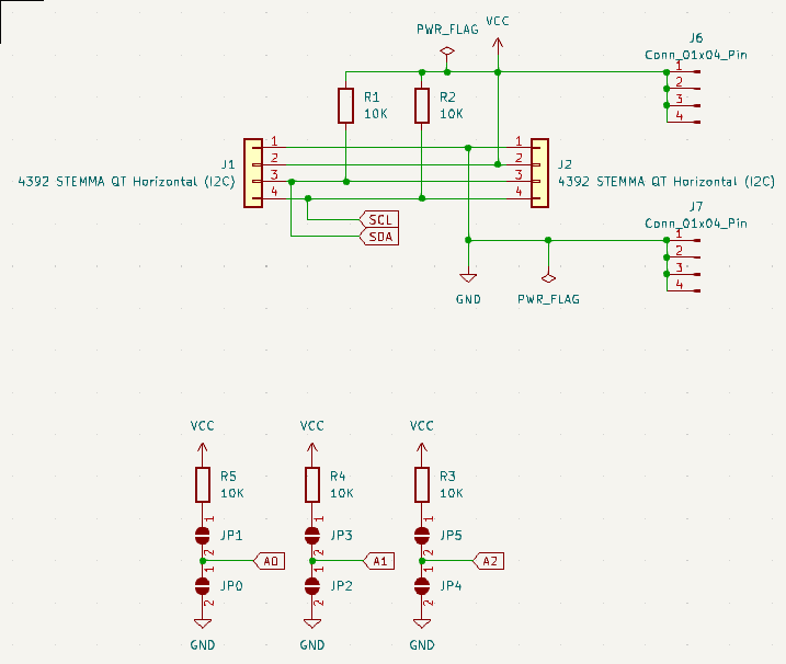
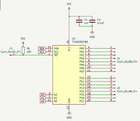
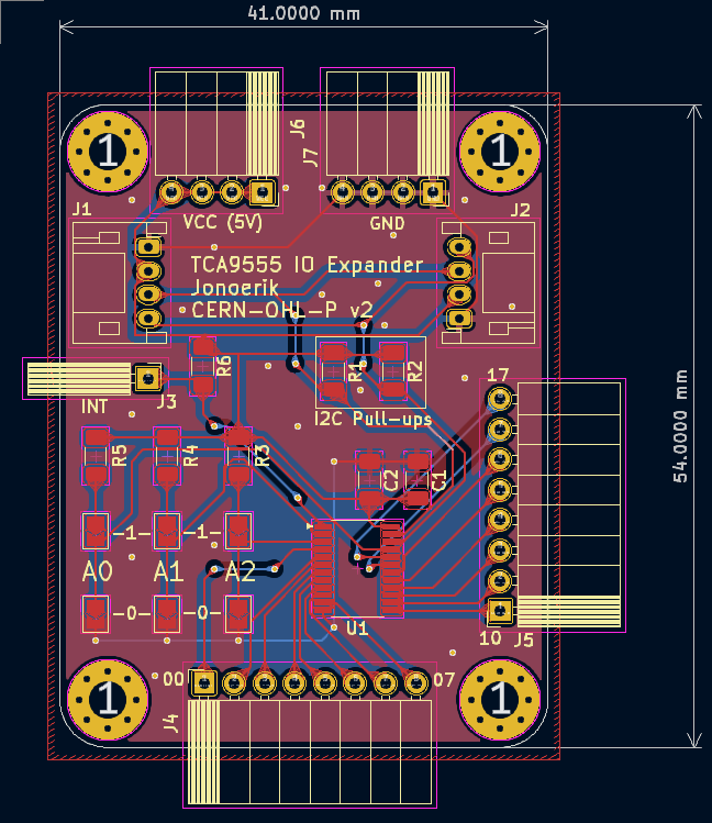
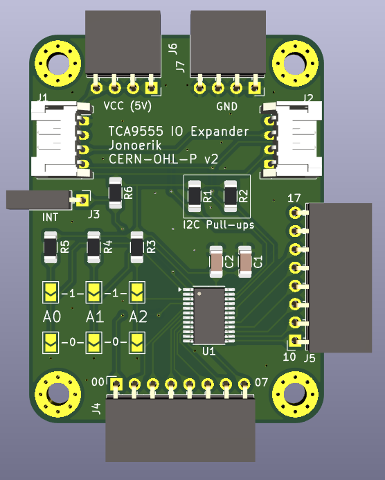
| Qty | Value | Footprint | References |
|---|---|---|---|
| 6 | 10K | Resistor_SMD:R_1206_3216Metric_Pad1.30x1.75mm_HandSolder | R1, R2, R3, R4, R5, R6 |
| 6 | SolderJumper_2_Open | io-expander-pcb:SolderJumper-2_P1.3mm_Open_TrianglePad1.0x1.5mm | JP0, JP1, JP2, JP3, JP4, JP5 |
| 4 | MountingHole_3.2mm_M3_Pad_Via | MountingHole:MountingHole_3.2mm_M3_Pad_Via | REF1, REF2, REF3, REF4 |
| 2 | 4392 STEMMA QT Horizontal (I2C) | Connector_JST:JST_PH_S4B-PH-K_1x04_P2.00mm_Horizontal | J1, J2 |
| 2 | Conn_01x04_Pin | Connector_PinSocket_2.54mm:PinSocket_1x04_P2.54mm_Horizontal | J6, J7 |
| 2 | Conn_01x08_Pin | Connector_PinSocket_2.54mm:PinSocket_1x08_P2.54mm_Horizontal | J4, J5 |
| 1 | 0.1uF | Capacitor_SMD:C_1206_3216Metric_Pad1.33x1.80mm_HandSolder | C2 |
| 1 | 1uF | Capacitor_SMD:C_1206_3216Metric_Pad1.33x1.80mm_HandSolder | C1 |
| 1 | Conn_01x01_Pin | Connector_PinSocket_2.54mm:PinSocket_1x01_P2.54mm_Horizontal | J3 |
| 1 | TCA9555PWR | Package_SO:TSSOP-24_4.4x7.8mm_P0.65mm | U1 |


Biacco42/modulo-ergo42
これは Beta バージョンの組み立てガイドです。Alpha 版は Alpha ブランチのドキュメントを参照してください。


lastlxrd/Pogopo
Open-source modular ESP32-S3 handheld console featuring custom hardware, a Sharp Memory LCD, pogopoOS, emulation, motion controls, audio, haptics, and expandable modules.

AnhadSawhney/MechanicalKeyCalculator
These are the CAD files for a calculator with mechanical keyswitches.

It measures 41 × 54 mm and has 2 copper layers, 1.6 mm thick.
26 parts, built around the TCA9555PWR(UMW). The full list of its parts is on this page, with links to each part's symbol and footprint where PCBKit's library has them.
From the jonoerik/io-expander-pcb repository on GitHub, at the commit this page was made from: the board is io-expander-pcb.kicad_pcb and its schematic io-expander-pcb.kicad_sch. PCBKit opens the board in the browser, with nothing to install.
Its repository states no licence, so its author keeps all rights: ask jonoerik before reusing the design.