
4 layers138.2 × 200.4 mm

 Biacco42/modulo-ergo4210
これは Beta バージョンの組み立てガイドです。Alpha 版は Alpha ブランチのドキュメントを参照してください。
Modulo ergo42 is an open-source printed circuit board by Biacco42, from the Biacco42/modulo-ergo42 repository on GitHub. It is a 2-layer board of 137.2 × 80 mm with 56 parts on 41 nets, routed with 369 tracks and 35 vias.
It is built around the TCA9555PWR(UMW). Its parts include 29 switches, 4 capacitors, 4 connectors, 3 resistors and 2 ICs.
これは Beta バージョンの組み立てガイドです。Alpha 版は Alpha ブランチのドキュメントを参照してください。
※フラックス必須です
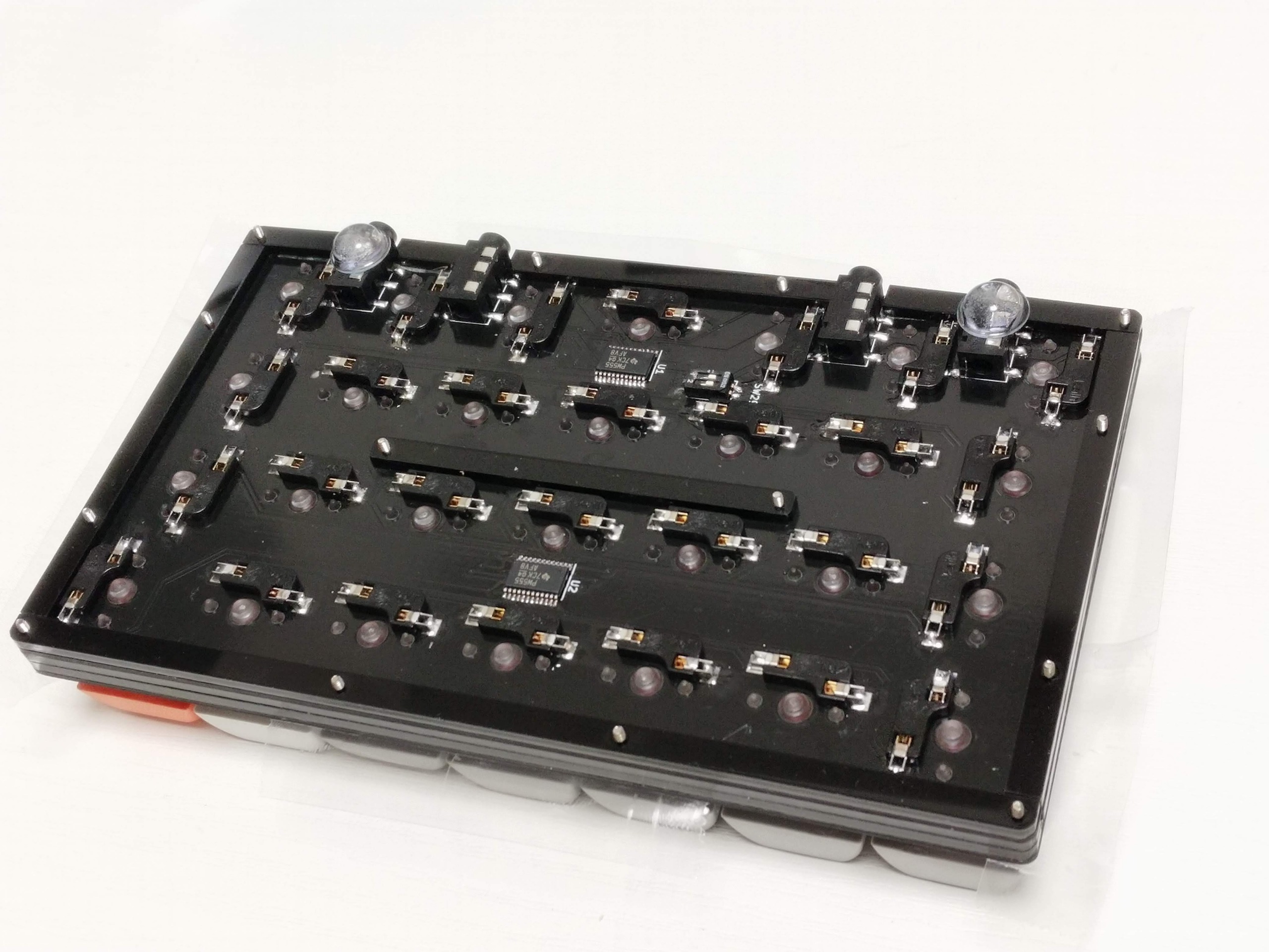
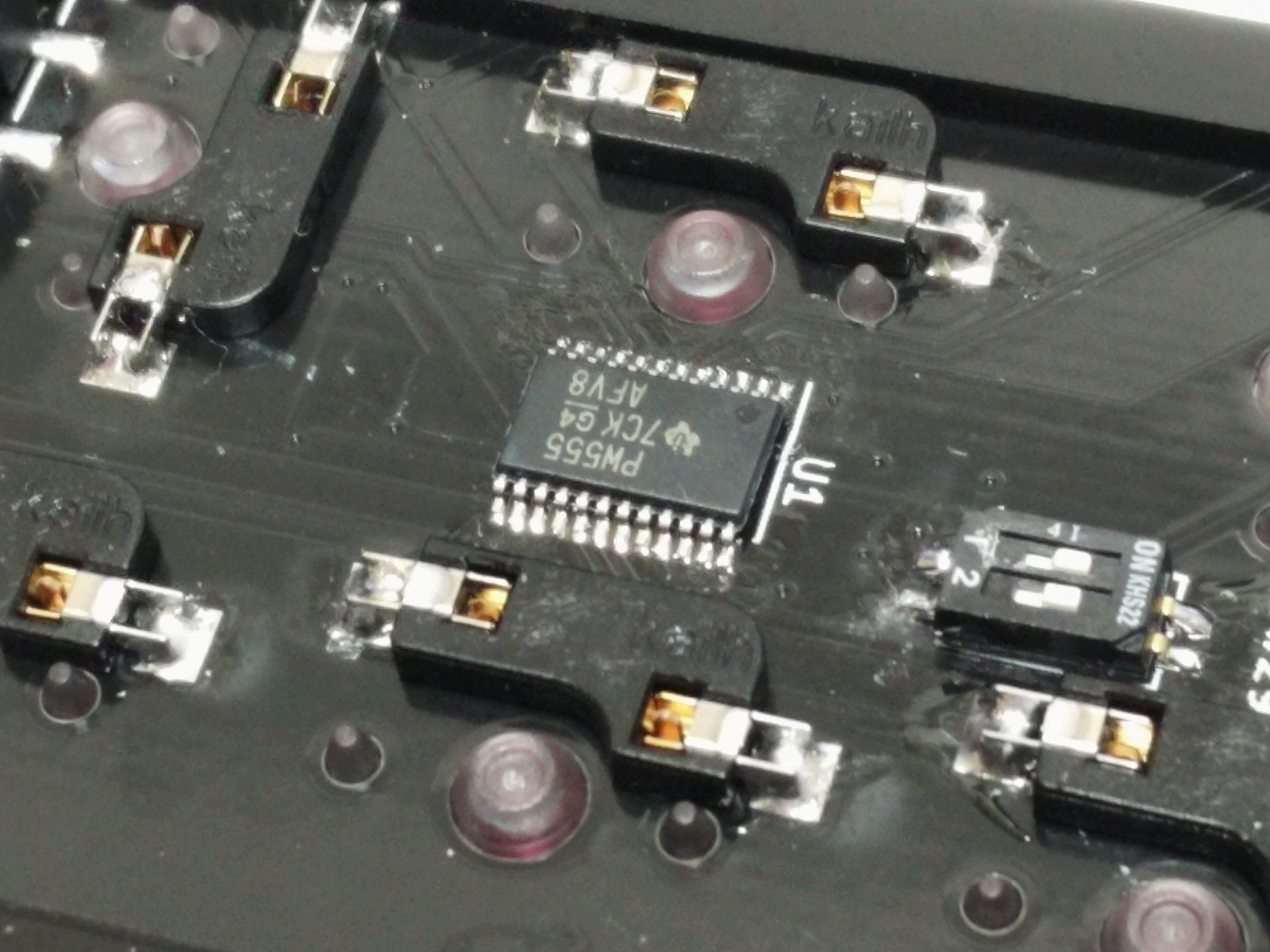
書き込み等開発環境について詳しくは、KbD Pre を参照するか、@Biacco42 までお問い合わせください。現在動作するファームウェアは こちらのリポジトリ の feature/modulo-ergo42-proto の keyboard/modulo/rev2 配下にあります。
| Qty | Value | Footprint | References |
|---|---|---|---|
| 28 | SW_Push | library:Kailh_Socket | SW1, SW2, SW10, SW11, SW12, SW13, SW14, SW15, SW16, SW17, SW18, SW19, SW20, SW21, SW22, SW23 +12 |
| 14 | Screw_Hole | library:Screw_Hole | , , , , , , , , , , , , , |
| 4 | AudioJack4 | library:TRRS_SMD_PJ320 | J1, J2, J3, J4 |
| 2 | 1 MΩ | Resistor_SMD:R_0603_1608Metric | R2, R3 |
| 2 | 1 uF | Capacitor_SMD:C_0603_1608Metric | C3, C4 |
| 2 | 100 nF | Capacitor_SMD:C_0603_1608Metric | C1, C2 |
| 2 | TCA9555PWR | Package_SO:TSSOP-24_4.4x7.8mm_P0.65mm | U1, U2 |
| 1 | 10 kΩ | Resistor_SMD:R_0603_1608Metric | R1 |
| 1 | SW_DIP_x02 | library:DipSwitch | SW29 |


lastlxrd/Pogopo
Open-source modular ESP32-S3 handheld console featuring custom hardware, a Sharp Memory LCD, pogopoOS, emulation, motion controls, audio, haptics, and expandable modules.

AnhadSawhney/MechanicalKeyCalculator
These are the CAD files for a calculator with mechanical keyswitches.


It measures 137.2 × 80 mm and has 2 copper layers, 1.6 mm thick.
56 parts, built around the TCA9555PWR(UMW). The full list of its parts is on this page, with links to each part's symbol and footprint where PCBKit's library has them.
From the Biacco42/modulo-ergo42 repository on GitHub, at the commit this page was made from: the board is modulo-ergo42/modulo-ergo42.kicad_pcb. PCBKit opens the board in the browser, with nothing to install.
Its repository states no licence, so its author keeps all rights: ask Biacco42 before reusing the design.