Custom PCB data logger for motorcycle racing: GPS position + IMU motion data, logged to a microSD card, with an e-Paper status display. Built around an ESP32-S3 (WiFi/BT built in) so it can also stream/sync over WiFi.
RaceTracker is an open-source printed circuit board by jonaschramm, from the jonaschramm/race-tracker repository on GitHub. It is a 4-layer board of 50.2 × 72.4 mm with 135 parts on 101 nets, routed with 2,200 tracks and 158 vias.
It is built around the NINA-W102-01B, BQ24195LRGE and MF-FSMF050X-2, with the PMEG6020ER, BLM18PG471SN1 and BSS138PS among its other parts. Its parts include 52 resistors, 39 capacitors, 8 diodes, 7 ICs and 5 connectors. It belongs with the radio and wireless boards of this library.
Custom PCB data logger for motorcycle racing: GPS position + IMU motion data,
logged to a microSD card, with an e-Paper status display. Built around an
ESP32-S3 (WiFi/BT built in) so it can also stream/sync over WiFi.
Current version: V3 (ESP32-S3)
This is the active, current board. Everything else in this repo (see
History / older versions below) is superseded —
kept for reference only, not under active development.
Open that project file in KiCad (10.0.5 or newer) — schematic
(RaceTracker_v3.kicad_sch) and PCB (RaceTracker_v3.kicad_pcb) are
alongside it.
Status
Schematic: ERC clean (0 violations).
PCB: fully routed by hand, kicad-cli pcb drc --severity-all → 0 errors
(a handful of expected warnings only — see below).
Board: 4-layer, ~56×66mm with rounded corner bosses for 4× M2 mounting
holes.
BOM: all 44 parts have a manufacturer part number and LCSC code (or
DigiKey, where LCSC doesn't carry the part) in the schematic symbol
properties — see bom/bom.csv.
Known, expected DRC warnings (not bugs):
lib_footprint_mismatch on J1, J5, J6, SW1, U1 — these footprints were
deliberately hand-adjusted to match real component pad geometry (pulled
from the parts' own datasheets/reference designs) rather than the stock
KiCad library footprint. Do not run "Update Footprint from Library" on
these — it would silently overwrite the verified geometry.
Key components
Function
Part
MCU (WiFi + BT)
ESP32-S3-WROOM-1-N8 (U1)
IMU (6-axis)
Würth WSEN-ISDS (U4)
GPS
external module via J3 (2.54mm header, I2C) — no onboard GPS
Storage
microSD (J4)
Display
e-Paper via J6 (8-pin header)
Charging
MCP73831 Li-Ion charger (U2) + USB-C (J1)
3.3V rail
AP2112K-3.3 LDO (U3)
Debug
UART via J5 (4-pin header)
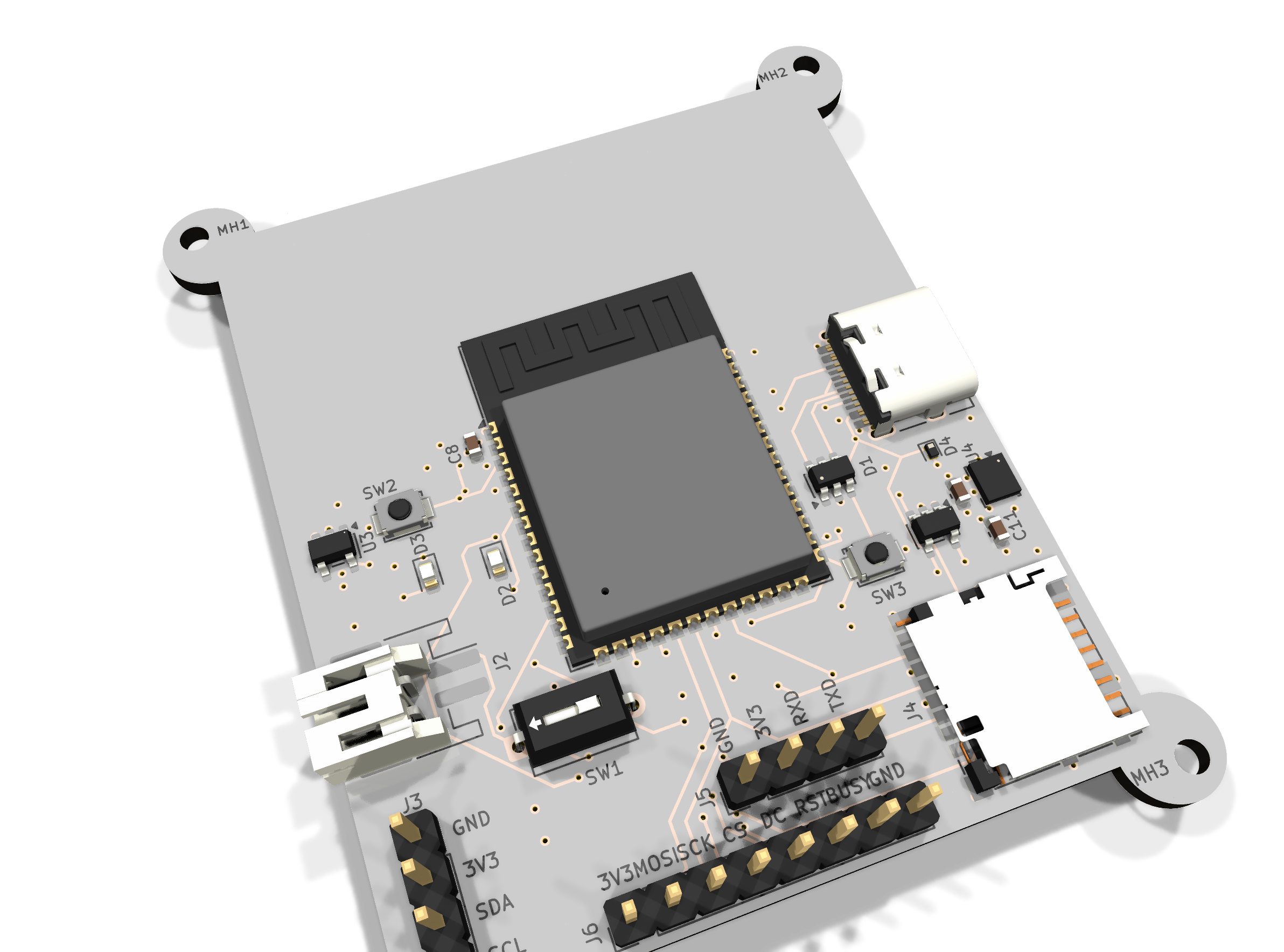
Pin-header connectors (J3, J5, J6) have their pin functions silkscreened
next to each pin so nothing gets miswired when the board is in hand without
the schematic open.
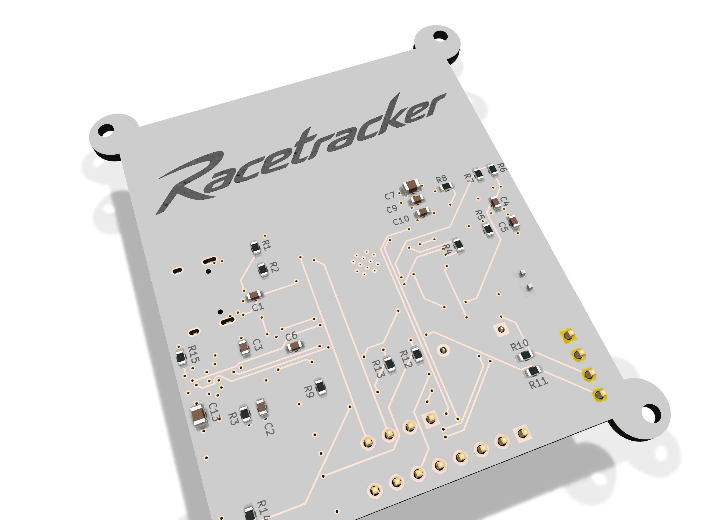
3D preview
Rendered straight from the board file (kicad-cli pcb render). A ready-to-embed,
interactive 3D model (quantized GLB, 3.4 MB — Draco was tried first but needs an
external decoder that not every embedding context can reach) lives at
RaceTracker.kicad_prj/V3 ESP32/RaceTracker_v3/3d/RaceTracker_v3.glb —
drop it into a <model-viewer> tag on any webpage to let
visitors spin the board around (also works in AR on phones). More stills in
assets/renders/.
Open items
Not yet done — flagging so nothing is assumed finished:
RF review — the ESP32-S3's on-board antenna keepout is respected on
the PCB, but nobody with hands-on RF experience has reviewed the
placement. Espressif's own guideline calls for ≥15mm clearance between
the antenna and any metal (enclosure, shielding) — the two mounting
holes closest to the antenna (top-left/top-right) are only ~3mm away, so
use nylon/plastic M2 screws there, not metal.
Enclosure / mechanical design — no current mechanical spec for a
case; board dimensions have changed several times, don't reuse an old one.
3D models / "finished" 3D view — not started.
Two BOM values are assumptions, not confirmed: D2/D3 LED colors (set to
red/green — schematic didn't specify a color) and SW1's exact MPN
(couldn't verify its physical dimensions against the datasheet).
27 pads show as "no net" against the schematic's auto-generated
placeholder nets — reviewed at a glance as genuinely-unused pins
(GPIO headroom, USB SBU lines), not individually re-verified.
Repo layout
text
RaceTracker.kicad_prj/
├── *.kicad_sch, RaceTracker.kicad_pcb   ← V1 (SAMD21 + onboard GPS/WiFi modules) — historical
├── V3 ESP32/RaceTracker_v3/             ← V3 (ESP32-S3) — CURRENT, see above
└── V3 ESP32/tools/                      ← pcbnew scripting helpers used while building V3
v2-simple/                                ← V2 (SAMD21, simplified, external GPS/WiFi) — abandoned mid-layout, superseded by V3
reference/eagle/                          ← imported Eagle symbols (Arduino MKR WiFi 1010) used as a source for V1/V2 parts
bom/bom.csv                               ← current BOM with MPN/LCSC/pricing data (V3)
History / older versions
V1 (RaceTracker.kicad_prj/*.kicad_sch at the repo root, tag
v1-full): original design — Arduino MKR WiFi 1010 (SAMD21) + separate
u-blox ZED-F9P RTK GPS module + MPU-6050 IMU. Fully routed, but heavier
and pricier than needed for the actual use case.
V2 / v2-simple: a pivot to drop the onboard GPS/WiFi modules in
favor of external pluggable headers, still on the SAMD21. Placement-only;
routing was never finished before the project moved to V3's ESP32-S3
(which has WiFi/BT built in, removing the need for a separate radio
module entirely). Kept for reference; not maintained.
Branches
main tracks the current state (V3). Historical exploration happened on
v2-simple — merged into main and not separately maintained going forward.
Custom PCB data logger for motorcycle racing: GPS position + IMU motion data, logged to a microSD card, with an e-Paper status display. Built around an ESP32-S3 (WiFi/BT built in) so it can also stream/sync over WiFi.
Node-RED Energy Harvesting dashboard example, weather forecast, temperature and humidty measurement. MQTT, ESP32, u-blox NINA-W10, HTU21D, IBM Cloud, CloudMQTT
LYFT is a sophisticated remote control for your IKEA BEKANT desk.
43 parts88GPL-3.0
Questions
How big is the RaceTracker PCB?
It measures 50.2 × 72.4 mm and has 4 copper layers, 1.6 mm thick.
What parts does the RaceTracker use?
135 parts, built around the NINA-W102-01B, BQ24195LRGE, MF-FSMF050X-2 and PMEG6020ER. The full list of its parts is on this page, with links to each part's symbol and footprint where PCBKit's library has them.
Where can I download the RaceTracker KiCad files?
From the jonaschramm/race-tracker repository on GitHub, at the commit this page was made from: the board is RaceTracker.kicad_prj/RaceTracker.kicad_pcb and its schematic RaceTracker.kicad_prj/GPS.kicad_sch. PCBKit opens the board in the browser, with nothing to install.
Can I use the RaceTracker design in my own project?
Its repository states no licence, so its author keeps all rights: ask jonaschramm before reusing the design.