4 layers406.4 × 254 mm

 joh/rgb-matrix3
RGB Matrix with USB and 48-bit colors!
Rgb matrix is an open-source printed circuit board by joh, from the joh/rgb-matrix repository on GitHub. It is a 4-layer board of 58 × 58 mm with 138 parts on 125 nets, routed with 1,409 tracks and 147 vias.
It is built around the STM32F405RGT6, 74AC244PC and LD3985M33R, with the ULN2803A and USBUF01W6 among its other parts. Its parts include 29 resistors, 22 capacitors, 16 connectors, 7 ICs and 2 diodes. It belongs with the lEDs and displays boards and the STM32 boards of this library.


The board is based around an STM32F405 microcontroller which drives each LED with 16-bit hardware PWM. It also handles USB, SPI, etc.
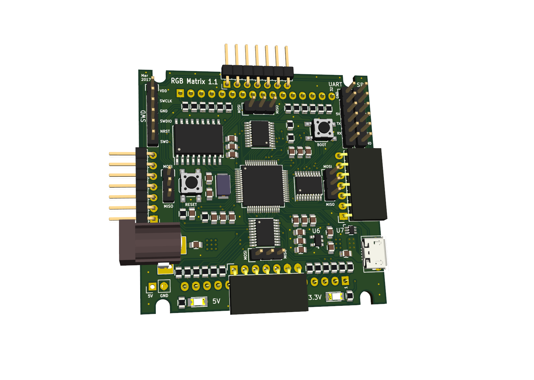
Each column is driven by SN74AC244 buffers, while the rows are driven by TBD62783 (common anode) or TBD62083/ULN2803A (common cathode).
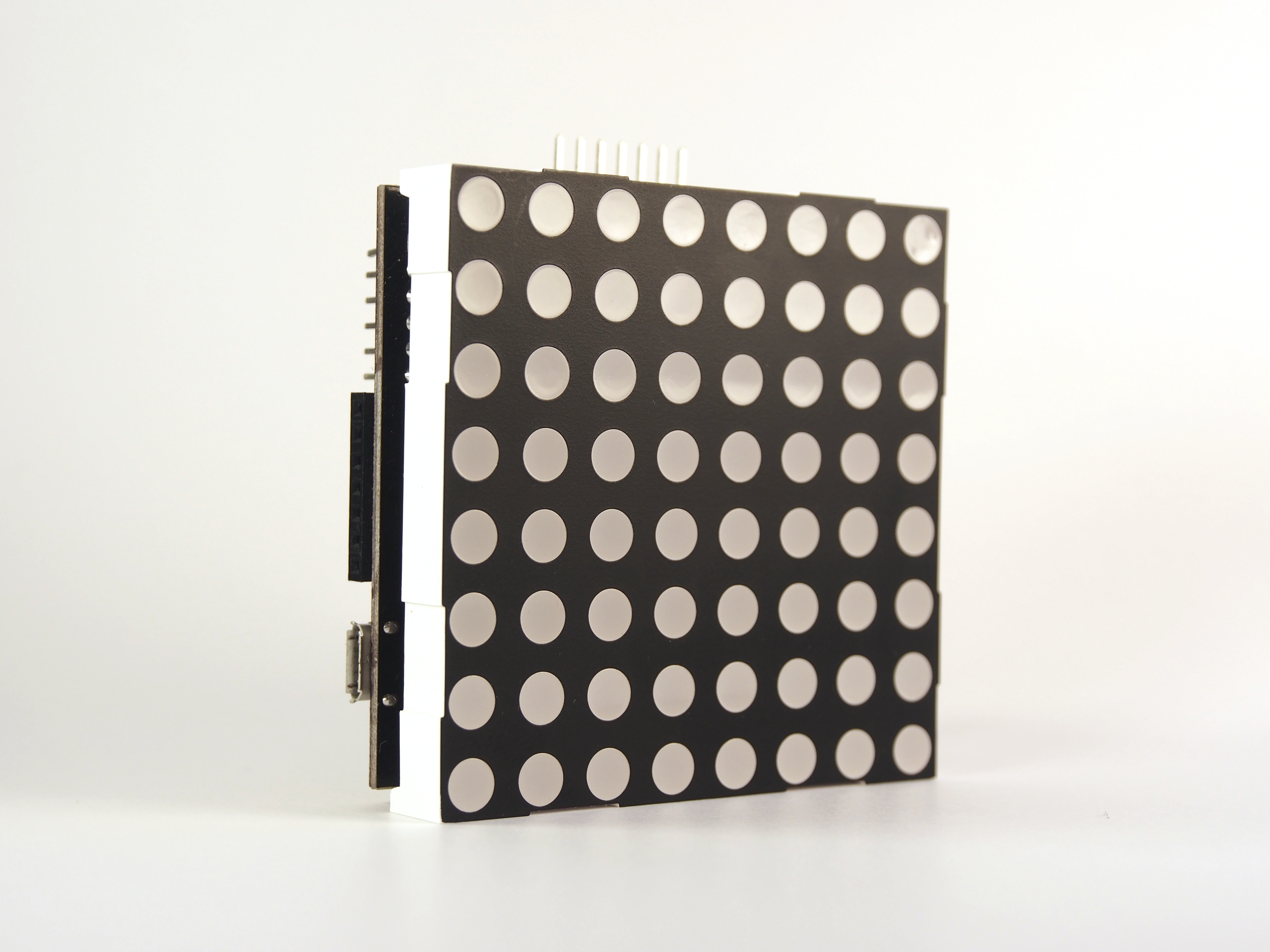
The PCB is 4 layers and connects with the LED matrix like a backpack.
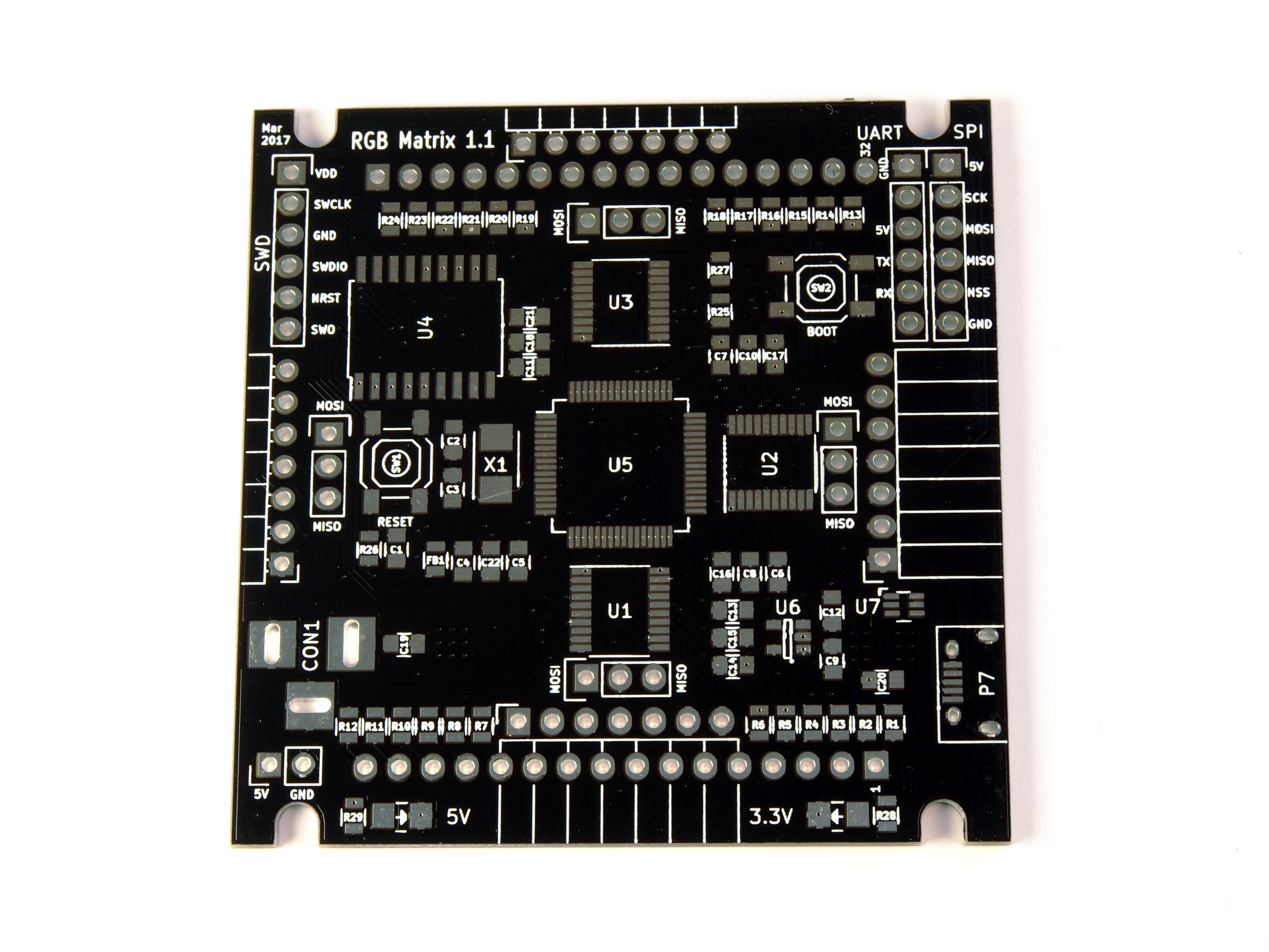
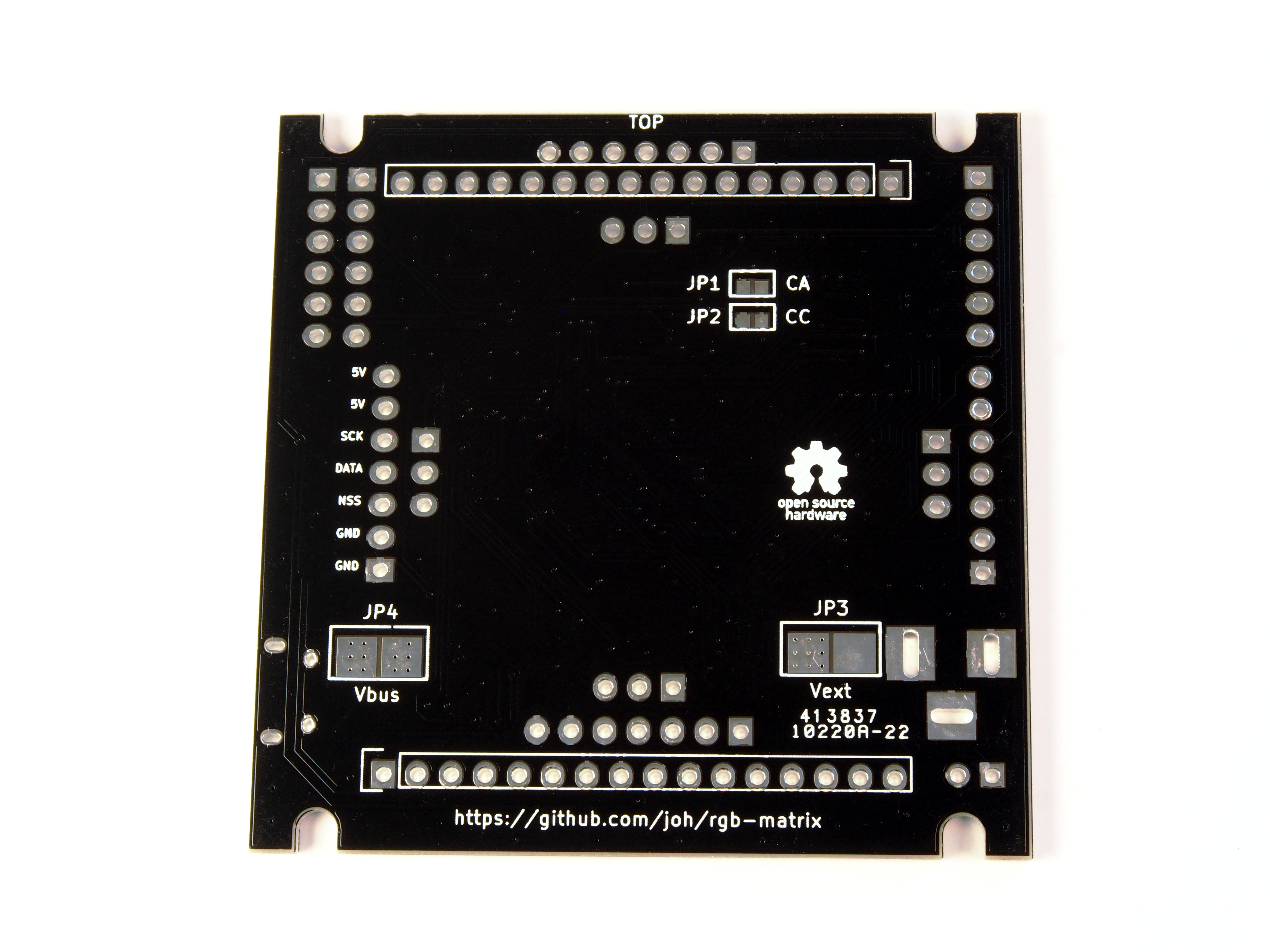
The PCB was designed to handle currents up to 6A, which typically means max 8 panels in series, with the limiting component being the pin headers.
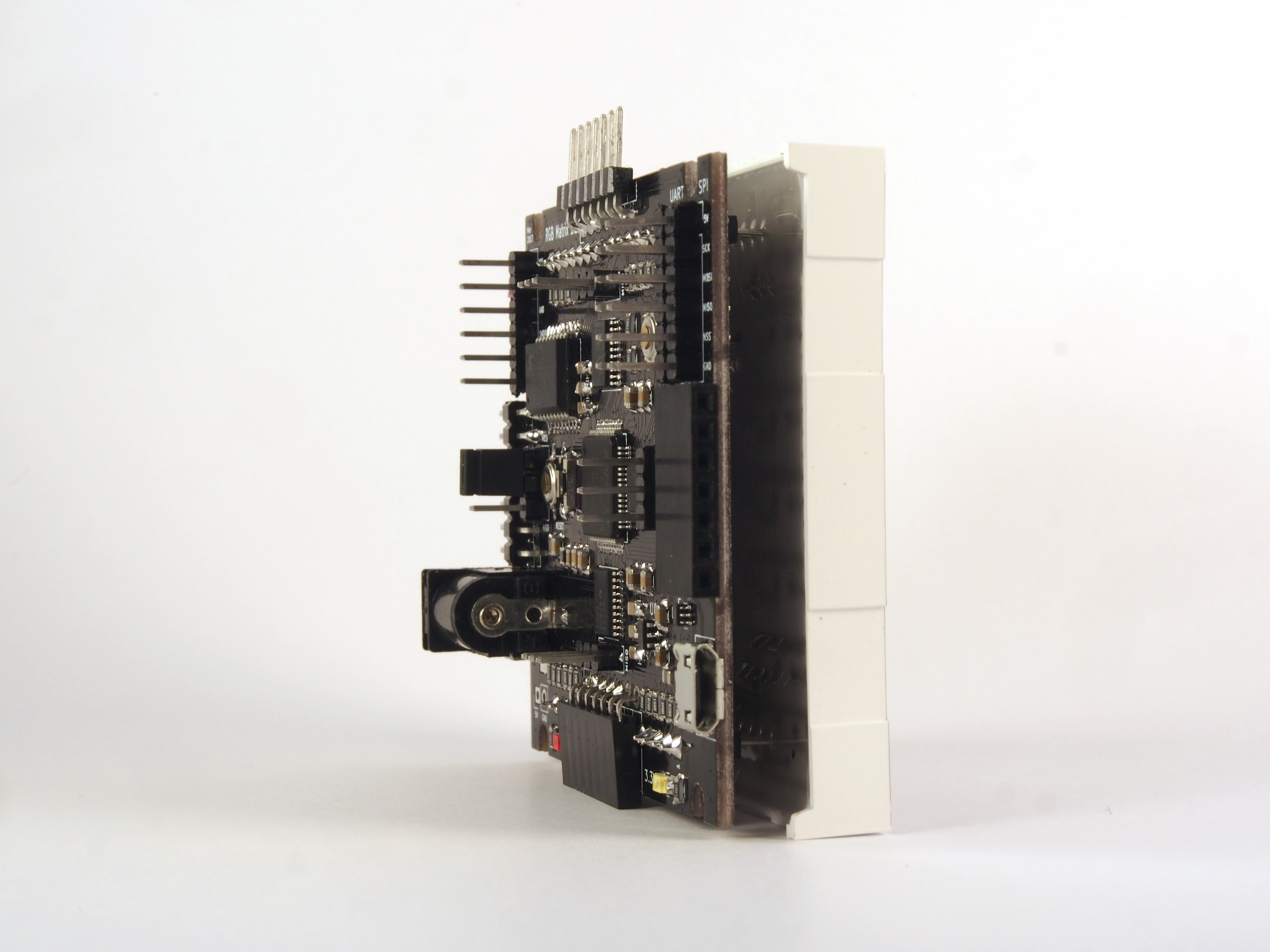
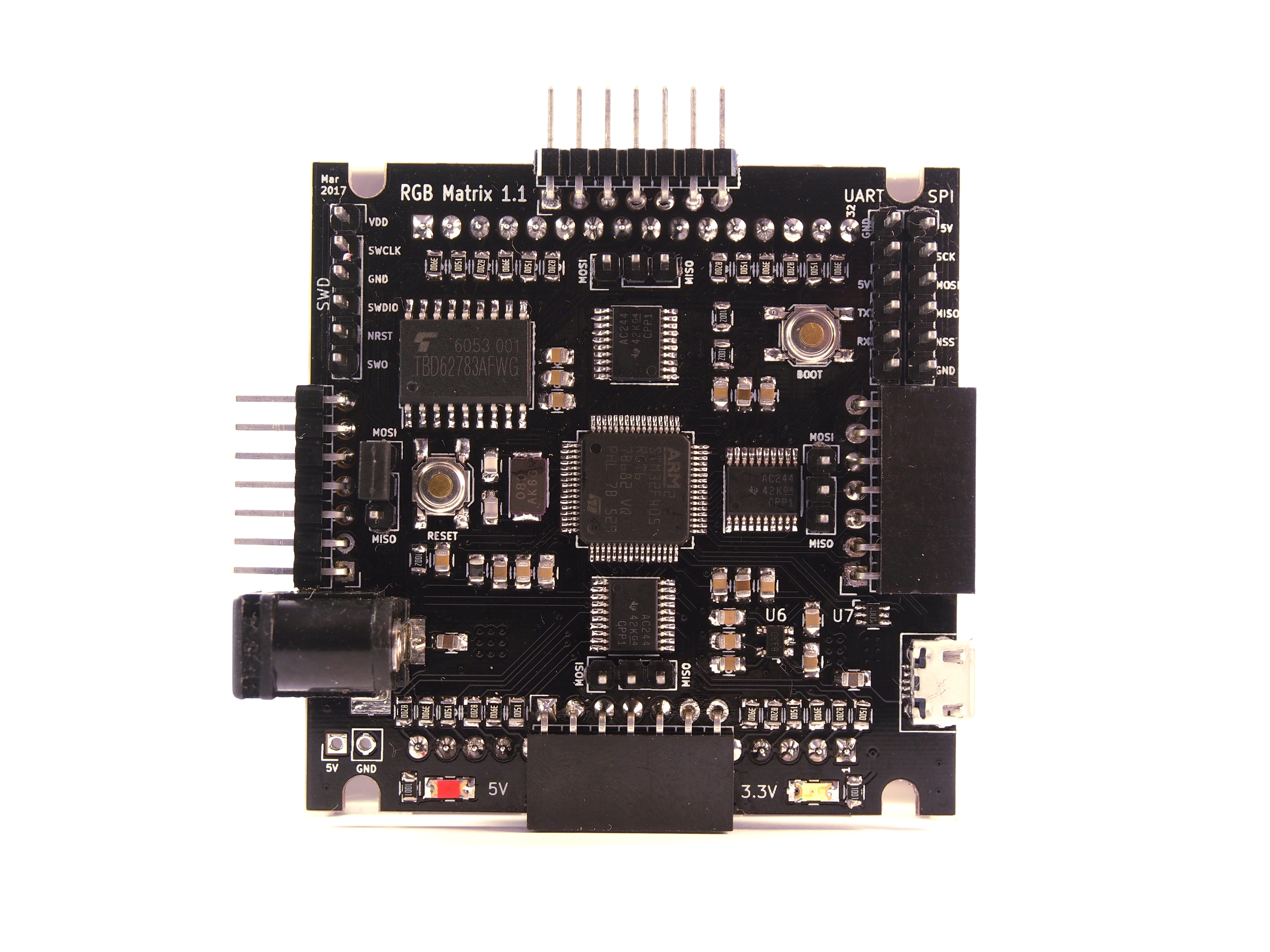
TODO
TODO: Some tips on soldering the board
TODO: info on components for CA/CC + jumpers
TODO: info about the jumpers
TODO: how to set jumpers
The board was originally designed for the 8x8 RGB Matrix sold by SparkFun (now sadly discontinued). Luckily there are plenty of displays on the market which are pin compatible. Some of them are listed below.
Any display with the same form factor should work, as long as the rows are on pins 7-10 and 23-26. Exactly which rows and columns are where is less important: they can be easily remapped in firmware.
TODO: picture
If you find a display that looks compatible which is not in the list below, please let me know so I can add it!
Tested displays:
Should work:
| Qty | Value | Footprint | References |
|---|---|---|---|
| 24 | 100 | rgb-matrix:R_0805 | R1, R2, R10, R11, R12, R13, R14, R15, R16, R17, R18, R19, R20, R21, R22, R23 +8 |
| 12 | 100nF | rgb-matrix:C_0805 | C1, C5, C6, C7, C11, C12, C15, C16, C17, C18, C21, C22 |
| 3 | 10k | rgb-matrix:R_0805 | R25, R26, R27 |
| 3 | 1uF | rgb-matrix:C_0805 | C4, C9, C14 |
| 3 | 74AC244 | Housings_SSOP:TSSOP-20_4.4x6.5mm_Pitch0.65mm | U1, U2, U3 |
| 2 | 10uF | rgb-matrix:C_0805 | C19, C20 |
| 2 | 1k | rgb-matrix:R_0805 | R28, R29 |
| 2 | 2.2uF | rgb-matrix:C_0805 | C8, C10 |
| 2 | 26pF | rgb-matrix:C_0805 | C2, C3 |
| 1 | 10nF | rgb-matrix:C_0805 | C13 |
| 1 | 3.3V | LEDs:LED_1206 | D1 |
| 1 | 5V | LEDs:LED_1206 | D2 |
| 1 | 8MHz | Crystals:Crystal_SMD_5032_2Pads | X1 |
| 1 | BOOT | Buttons_Switches_SMD:SW_SPST_SKQG | SW2 |
| 1 | CA | rgb-matrix:SMD-solder-bridge-1mm | JP1 |
| 1 | CC | rgb-matrix:SMD-solder-bridge-1mm | JP2 |
| 1 | EAST | Pin_Headers:Pin_Header_Straight_1x03 | P15 |
| 1 | FILTER | rgb-matrix:R_0805 | FB1 |
| 1 | LD3985M33R | TO_SOT_Packages_SMD:SOT-23-5 | U6 |
| 1 | MATRIX_BOT | Socket_Strips:Socket_Strip_Straight_1x16 | P1 |
| 1 | MATRIX_TOP | Socket_Strips:Socket_Strip_Straight_1x16 | P2 |
| 1 | NORTH | Pin_Headers:Pin_Header_Straight_1x03 | P13 |
| 1 | PEAST | Pin_Headers:Pin_Header_Angled_1x07_Pitch2.54mm | P11 |
| 1 | PNORTH | Pin_Headers:Pin_Header_Angled_1x07_Pitch2.54mm | P9 |
| 1 | PSOUTH | Socket_Strips:Socket_Strip_Angled_1x07 | P10 |
| 1 | PWEST | Socket_Strips:Socket_Strip_Angled_1x07 | P8 |
| 1 | RESET | Buttons_Switches_SMD:SW_SPST_SKQG | SW1 |
| 1 | SOUTH | Pin_Headers:Pin_Header_Straight_1x03 | P14 |
| 1 | SPI3 | Pin_Headers:Pin_Header_Straight_1x06 | P4 |
| 1 | STM32F405R | Housings_QFP:TQFP-64_10x10mm_Pitch0.5mm | U5 |
| 1 | SWD | Pin_Headers:Pin_Header_Straight_1x06 | P3 |
| 1 | UART5 | Pin_Headers:Pin_Header_Straight_1x06 | P5 |
| 1 | ULN2803A | Housings_SOIC:SOIC-18W_7.5x11.6mm_Pitch1.27mm | U4 |
| 1 | USBUF01W6 | rgb-matrix:SOT323-6L | U7 |
| 1 | USB_B | Connect:USB_Micro-B | P7 |
| 1 | VEXT | rgb-matrix:BARREL_JACK | CON1 |
| 1 | VEXT | Pin_Headers:Pin_Header_Straight_1x02_Pitch2.54mm | P6 |
| 1 | Vbus | rgb-matrix:SMD-solder-bridge-3mm | JP4 |
| 1 | Vext | rgb-matrix:SMD-solder-bridge-3mm | JP3 |
| 1 | WEST | Pin_Headers:Pin_Header_Straight_1x03 | P12 |
The 84 most common of 138 parts.
It measures 58 × 58 mm and has 4 copper layers, 1.6 mm thick.
138 parts, built around the STM32F405RGT6, 74AC244PC, LD3985M33R and ULN2803A. The full list of its parts is on this page, with links to each part's symbol and footprint where PCBKit's library has them.
From the joh/rgb-matrix repository on GitHub, at the commit this page was made from: the board is hardware/rgb-matrix.kicad_pcb. PCBKit opens the board in the browser, with nothing to install.
Its repository states no licence, so its author keeps all rights: ask joh before reusing the design.


maknoll/MRI_ADC_Probe
This repository includes all hard- firm- and software resources realated to MRI ADC Probe developed for measuring gradient fields in a running MRI scanner.
