

4 layers49.8 × 63 mm

UI for PCB smart exposure table
PiHat is an open-source printed circuit board by joelkoz, from the joelkoz/QwicktracePCB repository on GitHub, published under the MIT licence. It is a 2-layer board of 49.8 × 63 mm with 15 parts on 45 nets, routed with 140 tracks and 2 vias.
It is built around the BD139. Its parts include 9 connectors, 3 resistors, 1 IC, 1 diode and 1 transistor.

Qwicktrace PCB is the software component of the QwickFab PCB open source desktop circuit board fabrication system. The system dramatically reduces the time and skill required to make top quality single and double sided circuit boards for prototyping and one off use. Using QwickFab PCB, making a PCB is as simple as uploading your Gerber files to the Pro controller, selecting the process you wish to use to create the board, and then following the on-screen step by step instructions.
The QwickFab desktop fabrication system consists of three major hardware components and one optional one:
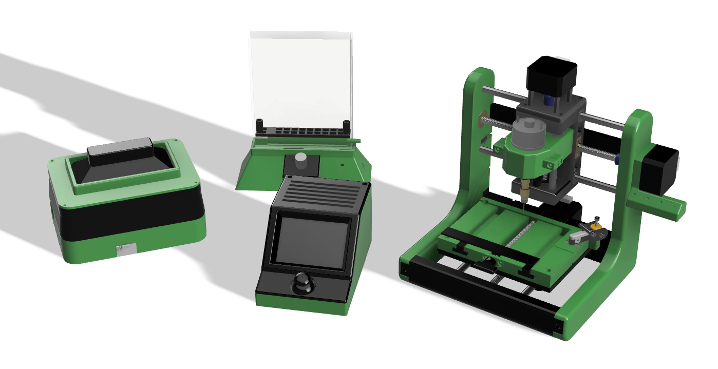
The Qwicktrace Pro Controller is small control device with touchscreen and joystick powered by a Raspberry Pi 4 and the software found in this repository. It is comprised of a software stack and UI for controlling the other two hardware components below. The Controller can run either of the two other components individually, or together as a complete desktop PCB fabrication system.
The Qwicktrace Exposure Table is a small device for quickly exposing photosensitive copper boards to ultraviolet light masked using a process called "Masked Stereolithography" (MSLA). The all new design of this exposure system adds an amber LED "safe light" for illuminating the mask for end user board positioning that is invisible to the photosenstive board.
The Qwickmill mini CNC is a small desktop CNC machine designed specifically for working with small printed circuit boards. It can quickly drill the holes needed by through hole components on boards processed with the Exposure table. It can also mill an entire PCB on blank copper boards using special ingraving bits. This is handy if your board is simple enough as to not need the better resolution of the exposure table, or if you are on a budget and would prefer not to spend the extra money on photosensitive boards. Finally, the Qwickmill can be used to cut board stock down to smaller sizes.
The QwickEtch Etching tank is a small container that can be used to quickly etch boards exposed with the Exposure table using a minimal mount of equipment. While any type of container can be used, the QwickEtch tank has an air pump powered agitator in in, removing the need for you to manually rock the etching tank.
The software on the Pro Controller (source code found on this repo) handles the more challenging aspects of making a PCB, such as aligning the drilling with the traces made on the exposure table, or positioning the opposite side of a board on a double sided PCB.
While the above hardware components make for a convenient set of tools, many Makers already have existing equipment they'd like to use in place of a QwickFab component. You are free to mix and match any or all of the components that you wish. You could in theory build NONE of the hardware components and simply run the Qwicktrace software on an old laptop or pre-existing Raspberry Pi build. The Qwickmill is built upon the open source standard Grbl controller. If you already own a CNC machines that uses Grbl, you can use that instead. It is easy to create a cable that connects from the Pro Controller to any CNC machine, such a 3018 or 1610. If you are on a budget, you can sometimes source a kit for one of these machines for less money than the individual parts for building the Qwickmill.
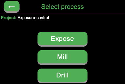
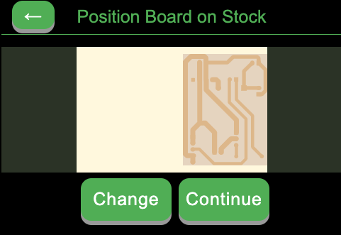
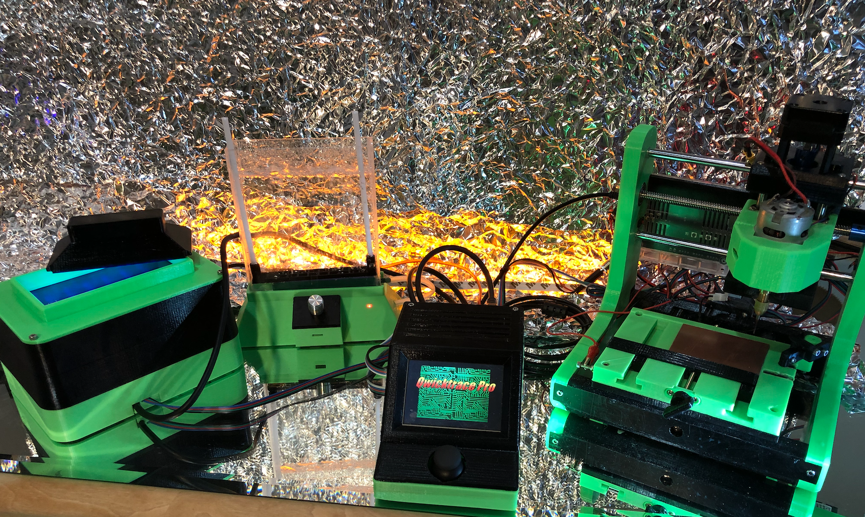
The Qwickfab Pro system is made from parts printed with your 3D printer as well as easy to obtain off the shelf parts. The
STL files for this project can be found here in this repo in the hardware/*/stl directories. A complete bill of materials can be
found in the docs directory.
Build instructions with project discussion is located on the project's Hackaday Project Page
To install the software on the Raspberry Pi, see the file Setting up Raspberry Pi, also in docs
The Qwicktrace user interface on the Pro Controller is a touchscreen app written in NodeJS/Javascript and built with the Electron framework. This UI is layered on top of a software stack comprised of many great open source software packages. These include:
For additional technical information on the Qwicktrace software architecture, see the docs directory

| Qty | Value | Footprint | References |
|---|---|---|---|
| 1 | 1K8 | Resistor_THT:R_Axial_DIN0207_L6.3mm_D2.5mm_P10.16mm_Horizontal | R1 |
| 1 | 1N4001 | Diode_THT:D_DO-41_SOD81_P10.16mm_Horizontal | D1 |
| 1 | 1k | Resistor_THT:R_Axial_DIN0207_L6.3mm_D2.5mm_P10.16mm_Horizontal | R3 |
| 1 | 20K | Resistor_THT:R_Axial_DIN0207_L6.3mm_D2.5mm_P10.16mm_Horizontal | R2 |
| 1 | AMZ_3A_MOD | jkoz_custom:Amazon_3A_Power_Module | U1 |
| 1 | BD139 | Package_TO_SOT_THT:TO-126-3_Vertical | Q1 |
| 1 | Buzzer | Connector_PinHeader_2.54mm:PinHeader_2x01_P2.54mm_Vertical | J9 |
| 1 | CNC | Connector_JST:JST_XH_B3B-XH-A_1x03_P2.50mm_Vertical | J5 |
| 1 | Fan | Connector_JST:JST_XH_B2B-XH-A_1x02_P2.50mm_Vertical | J4 |
| 1 | HDMI board | Connector_JST:JST_XH_B2B-XH-A_1x02_P2.50mm_Vertical | J3 |
| 1 | IDC16 | Connector_IDC:IDC-Header_2x08_P2.54mm_Vertical | J6 |
| 1 | Power | Connector_JST:JST_XH_B2B-XH-A_1x02_P2.50mm_Vertical | J2 |
| 1 | Pro Power | Connector_JST:JST_XH_B2B-XH-A_1x02_P2.50mm_Vertical | J8 |
| 1 | Raspberry_Pi_2_3 | pcb_etcher:PinSocket_2x20_P2.54mm_BacksideMount | J1 |
| 1 | UVPanel | Connector_JST:JST_XH_B5B-XH-A_1x05_P2.50mm_Vertical | J7 |


Matchboxscope/Matchboxscope
ESP32-based mini microscope for fluidic device observation


xtarke/automated_buggy
This shield connects microcontroller (MSP-EXP430FR2355) pins to the car's power board. Go to Power Board for more hardware information.

Aleksei327/STM32G474-Precision-Lab-Power-Supply
Precision 0–50 V programmable laboratory PSU with 1 mV/1 mA setting steps, hybrid synchronous-buck + linear regulation, STM32G474 control, INA228 metering, and layered hardware protection.
It measures 49.8 × 63 mm and has 2 copper layers, 1.6 mm thick.
15 parts, built around the BD139. The full list of its parts is on this page, with links to each part's symbol and footprint where PCBKit's library has them.
From the joelkoz/QwicktracePCB repository on GitHub, at the commit this page was made from: the board is hardware/qwicktrace-original/kicad/PiHat.kicad_pcb. PCBKit opens the board in the browser, with nothing to install.
Its repository publishes it under the MIT licence: you may reuse it on that licence's terms (keep the author's notice, and for a copyleft licence share your changes alike).