

2 layers106.9 × 48 mm

 prydin/classab-amp-mosfet9
MOSFET-based 50W Class AB amplifier
Classab amp is an open-source printed circuit board by prydin, from the prydin/classab-amp-mosfet repository on GitHub. It is a 2-layer board of 84.5 × 82.6 mm with 67 parts on 36 nets, routed with 288 tracks and 1 via.
It is built around the BD139, BD140 and IRFP240, with the IRFP9240 among its other parts. Its parts include 24 resistors, 13 transistors, 11 capacitors, 9 diodes and 5 connectors. It belongs with the audio and music boards of this library.
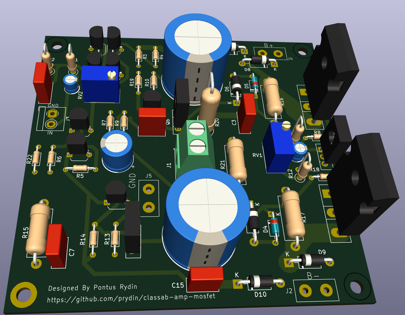
This amplifier has been built and tested and, at least subjectively speaking, sounds great. However, I'm not a professional designer and this is my first "serious" attempt at amplifier design. I invite you to build this amplifier if you like, but don't expect it to perform like a professionally designed high-end amplifier. That said, I think it sounds pretty darn good.
This is an updated version of the bipolar Class AB amplifier I designed a while ago that can be found here: https://github.com/prydin/classab-amp I tried to correct some of the mistakes (mostly in the PCB design) and I also wanted to try use MOSFETs for the output stage. I settled on the tried and tested IRFP240/9240 combination. Although not marketed as audio transistors, these devices have found their way into countless amplifier designs, perhaps most notably some of Nelson Pass' First Watt creations. I really like the way they're performing. They seem to run a lot cooler at the same quiescent current compared to their BJT counterparts. I'm also seeing less distortion and mostly concentrated on the second harmonic.
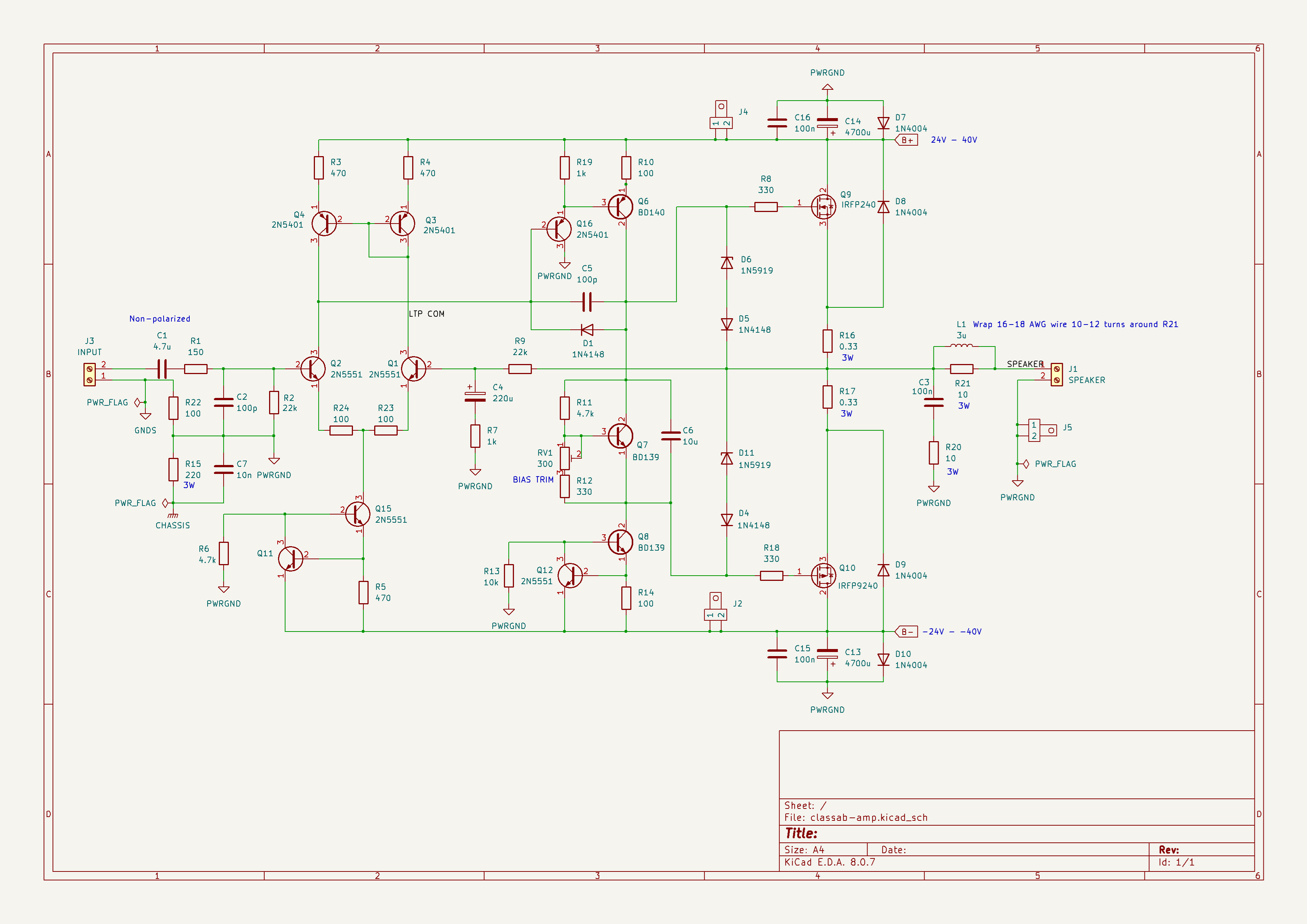
kicad - Schematic and PCB layout in KiCAD formatspice - LTSpice simulationsThe design is a simple single differential stage amplifier with a single ended, two transistor emitter coupled VAS driving two complementary MOSFETs on the output.
After the customary DC-blocking capacitor and RF filter, the signal is fed into a long tailed pair differential amplifier that's enhanced to an active current sink and current mirror loads. The active sink and load helps improve both distortion and frequency response. The bias current of the LTP is set to approximately 1.5mA. The LTP and its current mirrors are placed closely togethe for maximum heat condudctivity between the transistors. If so desired, they can be put into physical contact using a brace or a zip tied. The feedback is fed through a 22k/1k voltage divider, yielding about 23x (27dB) gain. This is a conservative estimate and may have to be adjusted when testing the physical build. The active current sink and load seem to offer a robustpower supply rejection.
I went for a very simple single-sided design here. I've gotten many suggestions that I should try a dual differential design instead, but the current design seems good enough, so I stuck with it. The VAS has a 220pF compensation capacitor which appears to be enough to provide ample phase margin.
The output stage is biased using a servo transistor driven by a constant current sink. The BD139 for the servo as chosen just because it's easy to mount on a heat sink together with the power components for good heat conductivity between components. A much less powerful transistor works too, but would have been harder to attach to the heat sink.
The output stage consists of a complementary pair made up of IRFP240/9240 MOSFETs with a 330ohm gate resistor. Before the signal reaches the speaker, it is passed througha snubber and an inductor to further improve stability.
Rather than the "base current thief" arrangement in the BJT version, I'm solely relying on a pair of zener diodes to keep the gate voltage about 5V above or below the source voltage. This limits the power to about 50W and results in fairly soft clipping.
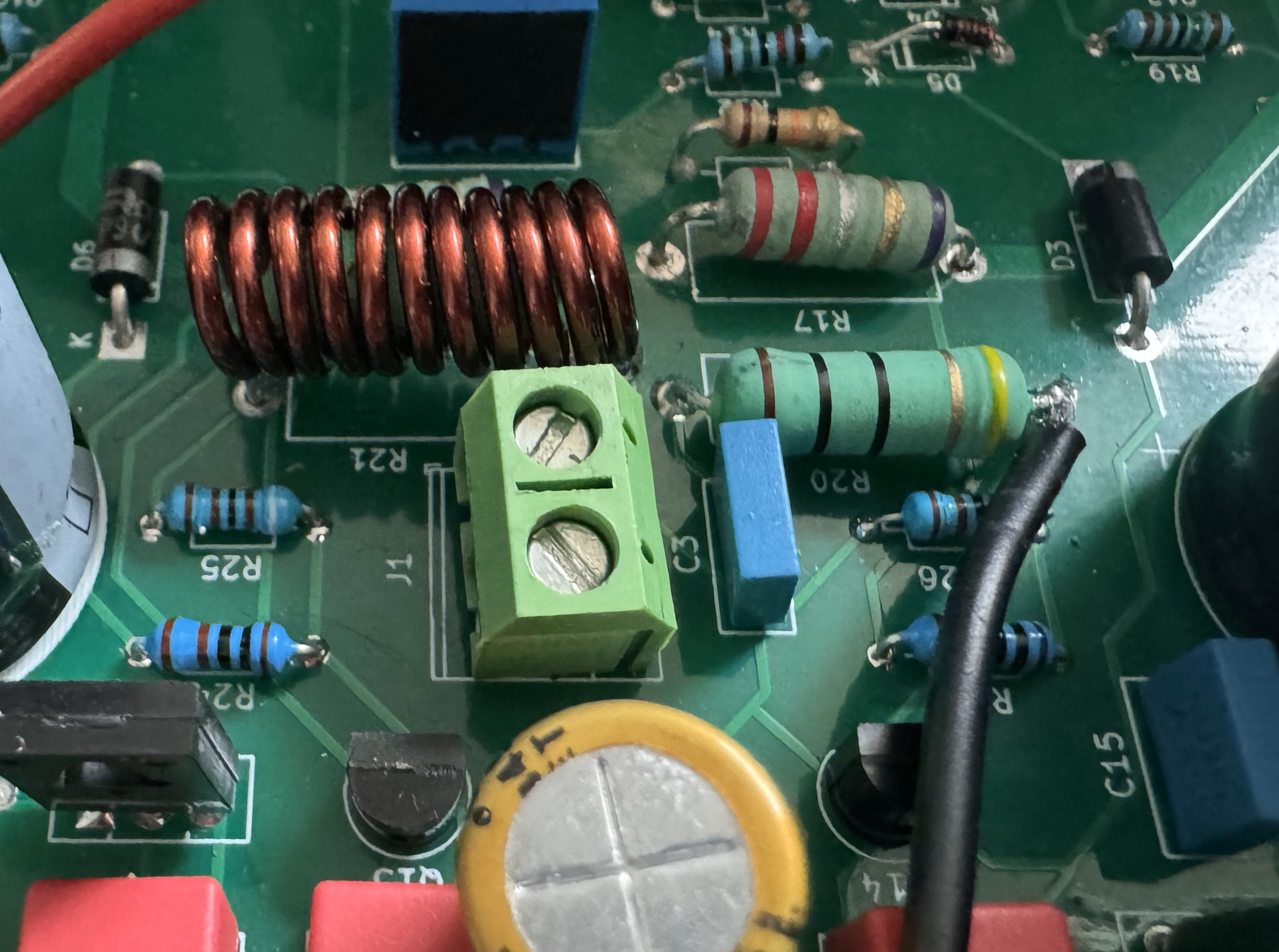
The output coil is realized simply by winding 10-12 turns of 16 AWG wire around R21. See the photo below!
Altough this hasn't been tested or thorouhgly analyzed, it should be possible to increase the rail voltages to +-40V, which yields about 160W according to simultions. For this to work, the gain needs to be made higher by increasing the value of the feedback resistor. The voltage limiting zener diodes on the gates also have to be adjusted.
The amplifier is intended to be powered by an unregulated linear power supply like the one supplied in this repository. Each amplifier board is fitted with 4700uF on each rail, per channel and the rectifier board has an additional 9400uF on each rail. In simulations, measurements and listening tests, this seems sufficient.
The amplifier has been tested with rail voltages ranging from +-24V to +-37V with good results. Obviously, higher output power requires more voltage. The recommended supply voltage range is +-24V to +-40V.
In my build, I'm using a 2x25V toroidial transformer. Where I live, this ended up giving me 2x39V rectified voltage, which is a bit overkill for 50W, but some extra headroom is never a bad thing.
I am NOT an expert at PCB design. In fact, I'm very much a novice and not very good at it, so the PCB layout is probably somewhat naive. In this design, I tried to create a star arrangement for the power ground. The power ground is loosely connected to the signal ground through a 100ohm resistor and to the chassis through a 220ohm resistor and a 10nF capacitor. This is slightly different from the prototype that I originally built, so you may have to tweak this if you experience hum. The prototype I'm currently using in my livingroom has no audible hum.
Mechnical design is not my forte, so you're probably best off to come up with your own design here. I went with a 11' x 10' metal case from Nobsound. This proved to be rather small with the beefy 250VA transformer I picked, so wire routing turned out to be a challenge. I wouldn't be offended if you called it a rat's nest. I used a pair of inexpensive finned aluminum heatsinks from Amazon and they seem to work very well. During casual listening at a moderate volume, they stay more or less room temperature.
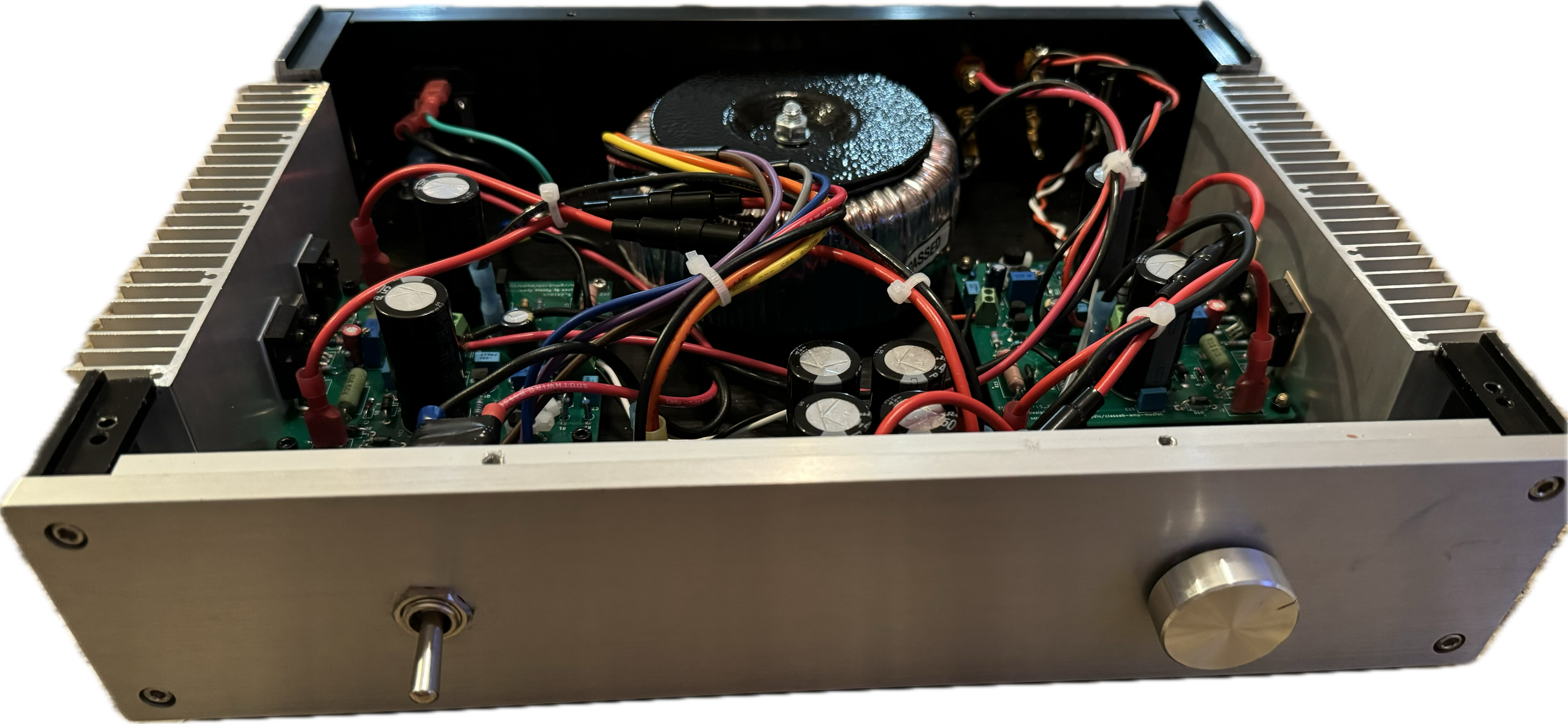
It is extremely important that Q7, Q9 and Q10 are thermally coupled, i.e. mounted on the same heat sink. Failure to do this may result in thermal runaway and catastrophic damage to the output stage!
You may also want to thermally couple the two transistor pairs in the input stage (R1 and R2, and R3 and R4 respectively). I just wrapped a piece if ziptie around them to make them touch.
This is the procedure I followed when bringing it up the first time. It saved me on the first bring-up since I had accidentally mixed up the transistors in the LTP which put DC on the speaker output.
All simulations are done with an 8 ohm resistive dummy load, 1V input at 1kHz.
At a fairly moderate quiescent current of 45mA, I get a THD20k of 0.003% at 30% power. A THD below 0.1% is considered to be inaudible, so these numbers are fine by me. I know there are audiophiles who insist on THD numbers <0.0001%, but I'm not one of them. Inaudible is just fine by me. The THD at full power (50W) is about 0.1%.
I unfortunately don't have the equipment to accurately measure THD in the lab, but it looks to be considerably below 0.1% (probably below 0.01%).
Fourier components of V(out)
DC component:-0.00638947

Harmonic	Frequency	 Fourier 	Normalized	 Phase  	Normalized
 Number 	  [Hz]   	Component	 Component	[degree]	Phase [deg]
    1   	 1.000e+3	 1.137e+1	 1.000e+0	   90.67°	    0.00°
    2   	 2.000e+3	 2.313e-4	 2.034e-5	  -82.88°	 -173.56°
    3   	 3.000e+3	 1.539e-4	 1.354e-5	  176.54°	   85.87°
    4   	 4.000e+3	 1.334e-4	 1.174e-5	  -87.58°	 -178.26°
    5   	 5.000e+3	 1.239e-5	 1.090e-6	 -166.62°	 -257.29°
    6   	 6.000e+3	 9.620e-5	 8.462e-6	  -84.00°	 -174.67°
    7   	 7.000e+3	 5.301e-5	 4.663e-6	    6.49°	  -84.19°
    8   	 8.000e+3	 6.785e-5	 5.968e-6	  -81.59°	 -172.26°
    9   	 9.000e+3	 6.897e-5	 6.067e-6	    8.04°	  -82.64°
   10   	 1.000e+4	 4.481e-5	 3.942e-6	  -78.43°	 -169.11°
   11   	 1.100e+4	 6.376e-5	 5.608e-6	    9.49°	  -81.19°
   12   	 1.200e+4	 2.633e-5	 2.316e-6	  -73.92°	 -164.59°
   13   	 1.300e+4	 5.062e-5	 4.453e-6	   10.82°	  -79.85°
   14   	 1.400e+4	 1.270e-5	 1.117e-6	  -65.17°	 -155.85°
   15   	 1.500e+4	 3.641e-5	 3.203e-6	   11.89°	  -78.79°
   16   	 1.600e+4	 4.245e-6	 3.734e-7	  -33.69°	 -124.37°
   17   	 1.700e+4	 2.420e-5	 2.129e-6	   12.70°	  -77.97°
   18   	 1.800e+4	 3.632e-6	 3.195e-7	   53.21°	  -37.47°
   19   	 1.900e+4	 1.499e-5	 1.318e-6	   12.97°	  -77.70°
   20   	 2.000e+4	 5.428e-6	 4.775e-7	   75.45°	  -15.22°
Harmonic Distortion: 0.003150%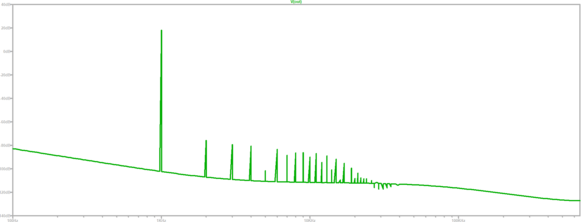
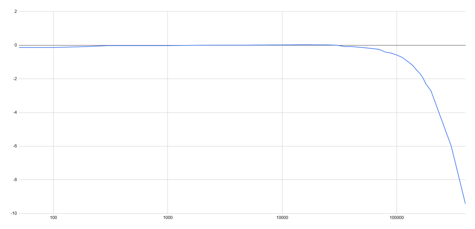
The amplifier has a 3dB bandwidth of about 250kHz, which is respectable, while not in the hardcore audiophile range, but it keeps any poles far away from the audible range to make both the amplitude and phase response vritually flat where it matters. I am of the opinion that nothing >20kHz has any impact on the listening experience.
All capacitor voltages are 50V and all resistor power ratings are 1/4W unless otherwise indicated. 1% tolerance resistors are recommended.
| Reference | Value | Footprint | Qty | Vendor | Part No |
|---|---|---|---|---|---|
| C1 | 33uF, non-polarized | Radial_D4.0mm_P2.00mm | 1 | Generic | |
| C2,C5 | 100pF | Rect_L7.2mm_W3.0mm_P5.00mm | 2 | Generic | |
| C4 | 220uF | Radial_D8.0mm_P5.00mm | 1 | Mouser | 871-B32529C1104J |
| C6 | 10uF | CRadial_D4.0mm_P2.00mm | 1 | Mouser | 710-860240672002 |
| C7 | 10nF | Rect_L7.2mm_W3.0mm_P5.00mm | 1 | Generic | |
| C13,C14 | 4700uF | CP_Radial_D18.0mm_P7.50mm | 2 | Mouser | 232-50PK4700MEFC18X4 |
| D4,D5 | 1N4148 | DO-35_SOD27_P7.62mm | 2 | Mouser | 512-1N4148 |
| D6,D11 | 1N5919 | DO-41_SOD81_P10.16mm | 2 | Mouser | 863-1N5919BRLG |
| D7,D8,D9,D10 | 1N4004 | DO-41_SOD81_P10.16mm | 4 | Mouser | 637-1N4004 |
| J1 | Terminal Block | TerminalBlock_Phoenix_MKDS-1,5-2_1x02_P5.00mm | 1 | Generic | |
| J2,J4,J5 | Spade connector, male | Pitch 5.08mm, hole 1.4mm | 3 | Generic | |
| J3 | Terminal Block | TerminalBlock_4Ucon_1x02_P3.50mm_Horizontal | 1 | Generic | |
| Q1,Q2,Q11,Q12,Q15 | 2N5551 | TO-92_Wide | 5 | Mouser | 583-2N5551-T |
| Q3,Q4,Q16 | 2N5401 | TO-92_Wide | 3 | Mouser | 583-2N5401-F |
| Q6 | BD140 | TO-126-3_Vertical | 1 | Mouser | 511-BD140-16 |
| Q7,Q8 | BD139 | TO-126-3_Vertical | 2 | Mouser | 511-BD139-16 |
| Q9 | IRFP240 | TO-247-3_Vertical | 1 | Mouser | 844-IRFP240PBF |
| Q10 | IRFP9240 | TO-247-3_Vertical | 1 | Mouser | 844-IRFP9240PBF |
| R1 | 150 | L6.3mm_D2.5mm_P2.54mm | 1 | Mouser | 660-MF1/4LCT52R151J |
| R2,R9 | 22k | L6.3mm_D2.5mm_P2.54mm | 2 | Mouser | MFR-25FTE52-22K |
| R3,R4,R5 | 470 | L3.6mm_D1.6mm_P7.62mm | 3 | Mouser | 660-MF1/4DCT52R4700F |
| R6,R11 | 4.7k | L3.6mm_D1.6mm_P7.62mm | 2 | Mouser | 660-MF1/4LCT52R472G |
| R7,R19 | 1k | L3.6mm_D1.6mm_P7.62mm | 2 | Mouser | 279-LR0204F1K0 |
| R8,R12,R18 | 330 | L3.6mm_D1.6mm_P7.62mm | 3 | Mouser | 660-MF1/4LCT52R331J |
| R10,R14,R22 | 100 | L3.6mm_D1.6mm_P7.62mm | 3 | Generic | |
| R13 | 10k | L3.6mm_D1.6mm_P7.62mm | 1 | Generic | |
| R15 | 220 / 3W | L11.9mm_D4.5mm_P15.24mm | 1 | Mouser | 603-FMP300JTF73-220R |
| R16,R17 | 0.33 / 3W | L11.9mm_D4.5mm_P15.24mm | 2 | Mouser | 71-PAC300003307FAC00 |
| R20,R21 | 10 / 3W | L11.9mm_D4.5mm_P15.24mm | 2 | Mouser | EP3WSS10RJ |
| RV1,RV2 | 300 | TRIM_T93YA103KT20 | 2 | Amazon | https://www.amazon.com/BOJACK-Multiturn-Trimmer-Potentiometer-Assortment/dp/B07WDCVGJV |
| Reference | Value | Footprint | Qty | Vendor | Part No |
|---|---|---|---|---|---|
| C1,C2,C5,C6 | 4700uF | CP_Radial_D18.0mm_P7.50mm | 4 | Mouser | 232-50PK4700MEFC18X4 |
| C3,C4,C7 | 100n | Rect_L7.2mm_W5.5mm_P5.00mm | 3 | Generic | |
| D1,D2,D3,D4 | GI754 | D_P600_R-6_P12.70mm | 4 | Mouser | 625-GI754-E3/73 |
| J1, J2, J3, J4, J5, J6 | Spade connector, male | Pitch 5.08mm, hole 1.4mm | 6 | Generic |
| Reference | Value | Footprint | Qty | Vendor | Part No |
|---|---|---|---|---|---|
| TR1 | 25V / 250VA | N/A | 1 | Avel Lindberg | Y236652 |
| Qty | Value | Footprint | References |
|---|---|---|---|
| 5 | 2N5551 | Package_TO_SOT_THT:TO-92_Wide | Q1, Q2, Q11, Q12, Q15 |
| 4 | 1N4004 | Diode_THT:D_DO-41_SOD81_P10.16mm_Horizontal | D7, D8, D9, D10 |
| 3 | 100 | Resistor_THT:R_Axial_DIN0204_L3.6mm_D1.6mm_P7.62mm_Horizontal | R10, R14, R22 |
| 3 | 100n | Capacitor_THT:C_Rect_L7.2mm_W3.0mm_P5.00mm_FKS2_FKP2_MKS2_MKP2 | C3, C15, C16 |
| 3 | 1N4148 | Diode_THT:D_DO-35_SOD27_P7.62mm_Horizontal | D1, D4, D5 |
| 3 | 2N5401 | Package_TO_SOT_THT:TO-92_Wide | Q3, Q4, Q16 |
| 3 | 470 | Resistor_THT:R_Axial_DIN0204_L3.6mm_D1.6mm_P7.62mm_Horizontal | R3, R4, R5 |
| 3 | ~ | footprints:Spade Connector | J2, J4, J5 |
| 2 | 0.33 | Resistor_THT:R_Axial_DIN0414_L11.9mm_D4.5mm_P15.24mm_Horizontal | R16, R17 |
| 2 | 100 | Resistor_THT:R_Axial_DIN0207_L6.3mm_D2.5mm_P2.54mm_Vertical | R23, R24 |
| 2 | 100p | Capacitor_THT:C_Rect_L7.2mm_W3.0mm_P5.00mm_FKS2_FKP2_MKS2_MKP2 | C2, C5 |
| 2 | 1N5919 | Diode_THT:D_DO-41_SOD81_P10.16mm_Horizontal | D6, D11 |
| 2 | 1k | Resistor_THT:R_Axial_DIN0204_L3.6mm_D1.6mm_P7.62mm_Horizontal | R7, R19 |
| 2 | 330 | Resistor_THT:R_Axial_DIN0204_L3.6mm_D1.6mm_P7.62mm_Horizontal | R8, R18 |
| 2 | 4700u | Capacitor_THT:CP_Radial_D18.0mm_P7.50mm | C13, C14 |
| 2 | BD139 | Package_TO_SOT_THT:TO-126-3_Vertical | Q7, Q8 |
| 1 | |||
| 1 | 10 | Resistor_THT:R_Axial_DIN0516_L15.5mm_D5.0mm_P5.08mm_Vertical | R20 |
| 1 | 10 | Resistor_THT:R_Axial_DIN0414_L11.9mm_D4.5mm_P15.24mm_Horizontal | R21 |
| 1 | 10k | Resistor_THT:R_Axial_DIN0204_L3.6mm_D1.6mm_P7.62mm_Horizontal | R13 |
| 1 | 10n | Capacitor_THT:C_Rect_L7.2mm_W3.0mm_P5.00mm_FKS2_FKP2_MKS2_MKP2 | C7 |
| 1 | 10u | Capacitor_THT:CP_Radial_D4.0mm_P2.00mm | C6 |
| 1 | 150 | Resistor_THT:R_Axial_DIN0207_L6.3mm_D2.5mm_P2.54mm_Vertical | R1 |
| 1 | 220 | Resistor_THT:R_Axial_DIN0414_L11.9mm_D4.5mm_P15.24mm_Horizontal | R15 |
| 1 | 220u | Capacitor_THT:CP_Radial_D8.0mm_P5.00mm | C4 |
| 1 | 22k | Resistor_THT:R_Axial_DIN0207_L6.3mm_D2.5mm_P2.54mm_Vertical | R2 |
| 1 | 22k | Resistor_THT:R_Axial_DIN0204_L3.6mm_D1.6mm_P7.62mm_Horizontal | R9 |
| 1 | 300 | footprints:TRIM_T93YA103KT20 | RV1 |
| 1 | 330 | Resistor_THT:R_Axial_DIN0207_L6.3mm_D2.5mm_P2.54mm_Vertical | R12 |
| 1 | 4.7k | Resistor_THT:R_Axial_DIN0207_L6.3mm_D2.5mm_P2.54mm_Vertical | R11 |
| 1 | 4.7k | Resistor_THT:R_Axial_DIN0204_L3.6mm_D1.6mm_P7.62mm_Horizontal | R6 |
| 1 | 4.7u | Capacitor_THT:CP_Radial_D4.0mm_P2.00mm | C1 |
| 1 | BD140 | Package_TO_SOT_THT:TO-126-3_Vertical | Q6 |
| 1 | INPUT | TerminalBlock_4Ucon:TerminalBlock_4Ucon_1x02_P3.50mm_Horizontal | J3 |
| 1 | IRFP240 | Package_TO_SOT_THT:TO-247-3_Vertical | Q9 |
| 1 | IRFP9240 | Package_TO_SOT_THT:TO-247-3_Vertical | Q10 |
| 1 | SPEAKER | TerminalBlock_Phoenix:TerminalBlock_Phoenix_MKDS-1,5-2_1x02_P5.00mm_Horizontal | J1 |
The 64 most common of 67 parts.


M-K-O-Hybrid-open-source/BUCK_manual_Process
the main aim of this design is the ease of the manual manufacturing process of this PCB and the availability of the component


It measures 84.5 × 82.6 mm and has 2 copper layers, 1.6 mm thick.
67 parts, built around the BD139, BD140, IRFP240 and IRFP9240. The full list of its parts is on this page, with links to each part's symbol and footprint where PCBKit's library has them.
From the prydin/classab-amp-mosfet repository on GitHub, at the commit this page was made from: the board is kicad/classab-amp.kicad_pcb and its schematic kicad/classab-amp.kicad_sch. PCBKit opens the board in the browser, with nothing to install.
Its repository states no licence, so its author keeps all rights: ask prydin before reusing the design.