4 layers100 × 100 mm
Rpi pico printer board
jackw01/pi-pico-printer-board
Tinkerer-friendly Klipper compatible 3D printer control board using Raspberry Pi Pico
224 parts42CERN-OHL-W-2.0

 jnjoaquin/SSDV3
A 12S battery eliminator circuit for UAS applications. Please see the UBCO Aerospace fork for the latest release.
SSDV3 is an open-source printed circuit board by jnjoaquin, from the jnjoaquin/SSDV3 repository on GitHub, published under the CERN-OHL-W-2.0 licence. It is a 4-layer board of 58.4 × 28.8 mm with 69 parts on 30 nets, routed with 192 tracks and 195 vias.
It is built around the LM5146RGY, BSZ146N10LS5 and BAT46WS, with the SM02B-GHS-TB(LF)(SN) and SM03B-GHS-TB(LF)(SN) among its other parts. Its parts include 23 capacitors, 17 resistors, 8 connectors, 6 diodes and 3 transistors.


This project has been migrated to the UBCO Aerospace Club 2025_SSDV3 fork.
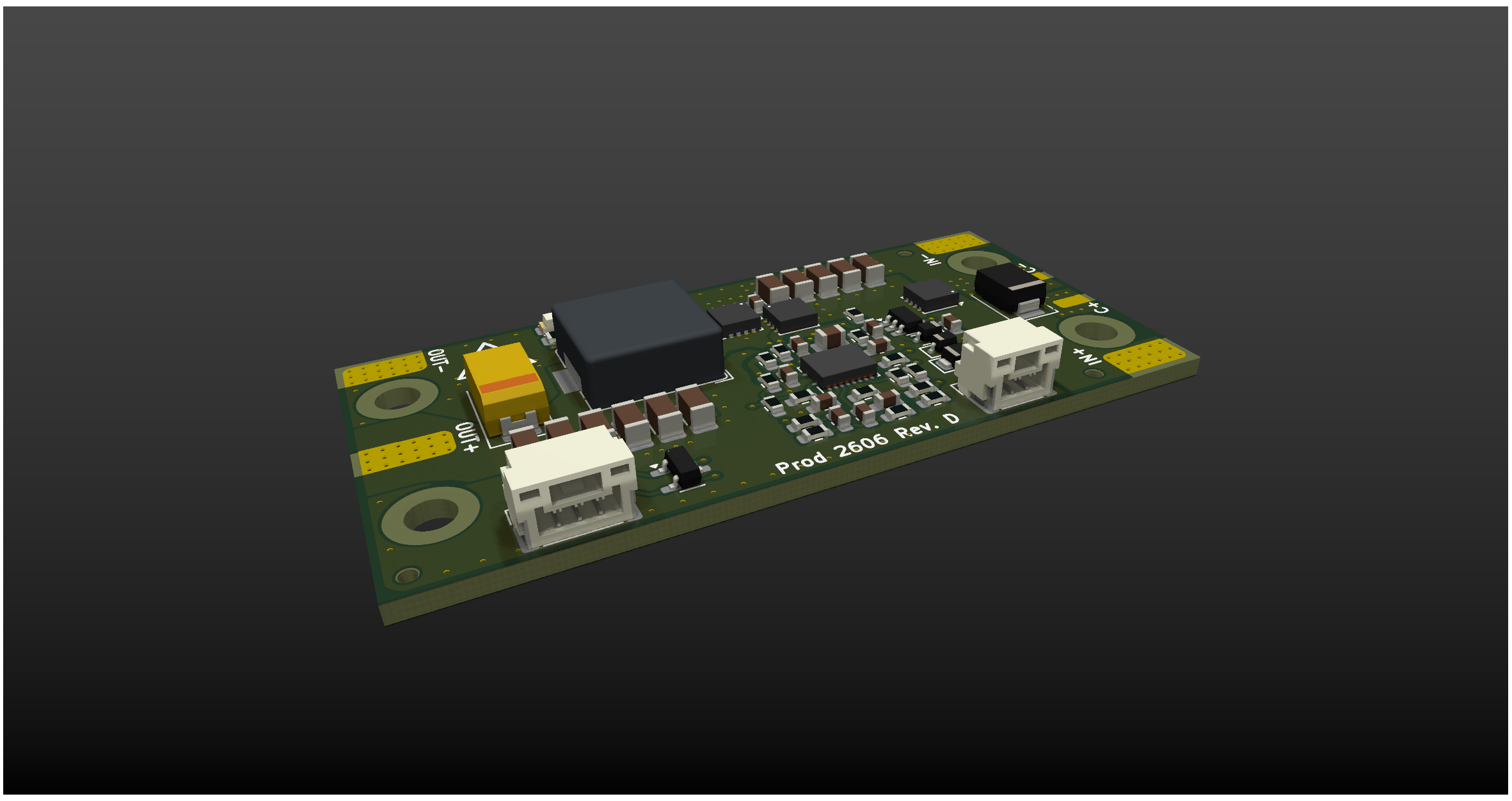
The SSDV3 is an independently-made, non-isolated DC/DC converter designed for unmanned aerial systems (UAS). The module is intended for converting 50V battery input down to 5-12V output at a maximum load of 8A. It acts as a reliable battery-eliminator circuit (BEC) through effective regulation in the presence of large line voltage and load current transients.
This design is motivated by the challenges encountered by the UBCO Aerospace Club with their Jellyfish quadcopter when powering auxiliary electronics off the drone's main battery. Lessons were learned through a variety of integration failures, investigations, and validation testing, and these experiences informed the development of version 3 of the Super Step Down series.
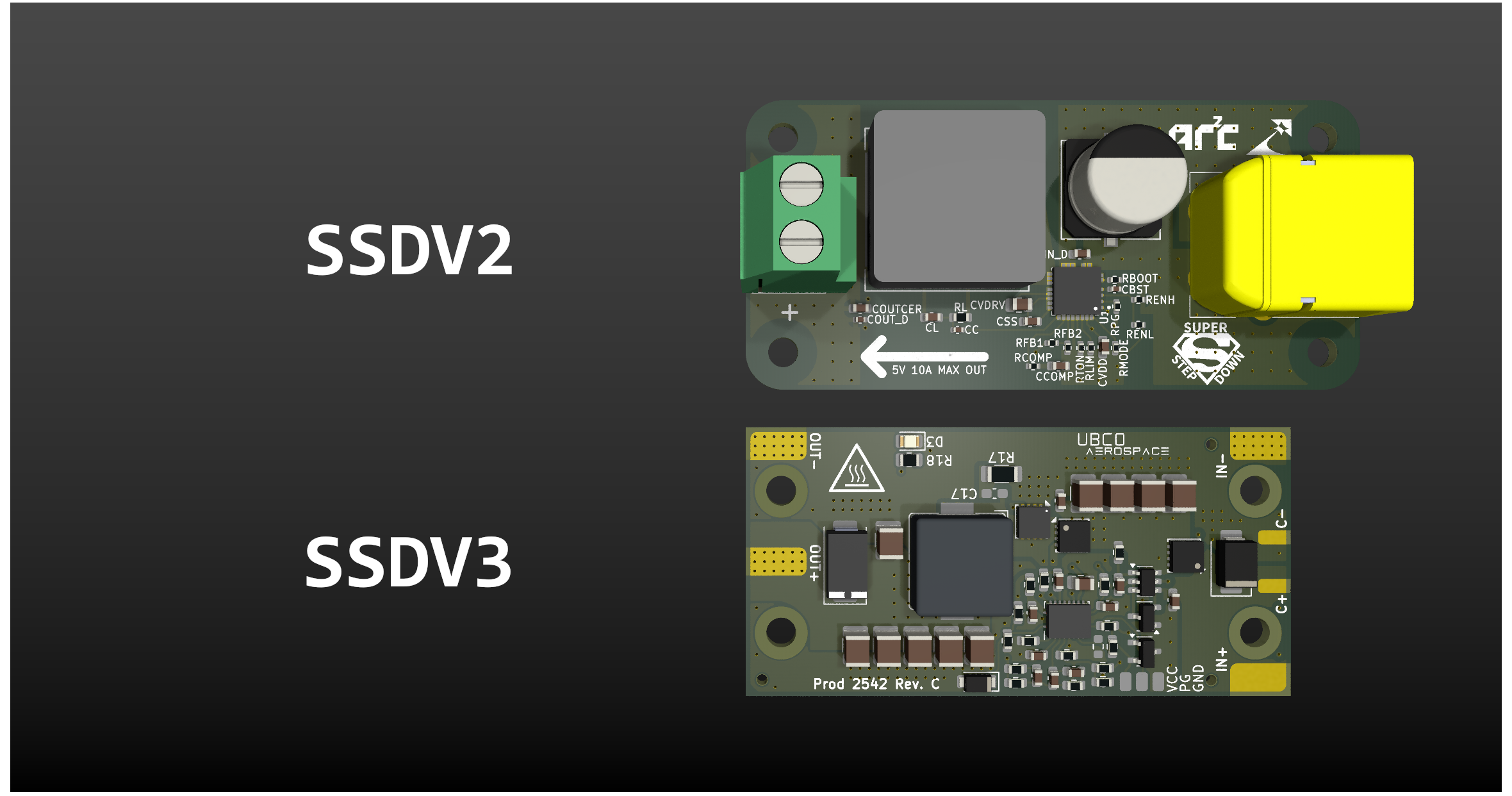
Improvements from the previous version:
| Input Voltage | 20-60V |
| Max Transient Voltage | 100V (clamping starts at 70V) |
| Output Voltage(s) | 5.1V, 7.4V, 9.6V, 12V |
| Max Output Current* | 8A |
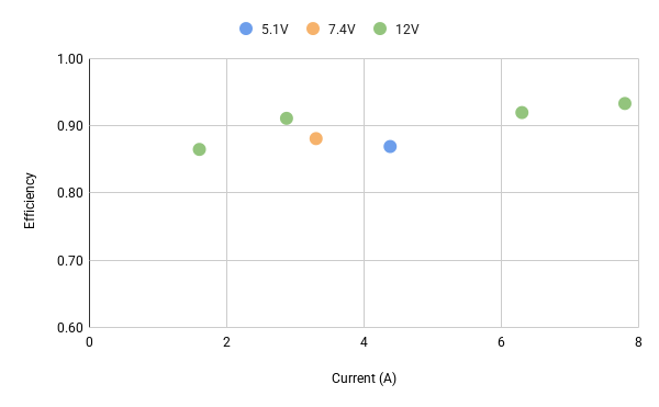
| Typical Efficiency | 88% |
| Est. Voltage Overshoot | 200mV |
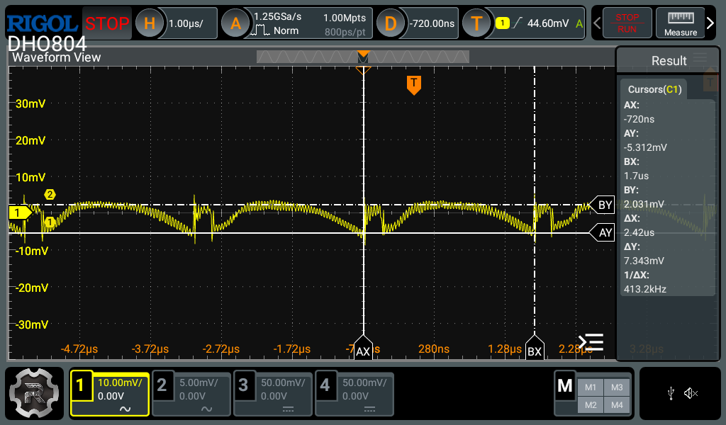
Voltage ripple at 5.1V Output
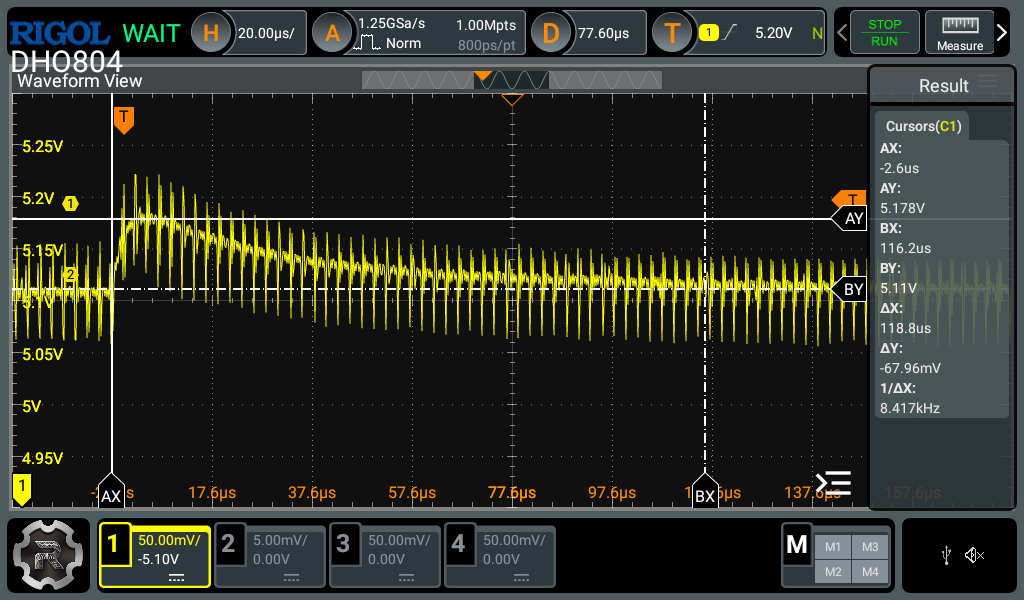
Transient response of 5.1V 0-5A Output
Efficiency Measurements
Copyright © Julian Joaquin 2026
Hardware Source Licensed under CERN-OHL-W version 2
| Qty | Value | Footprint | References |
|---|---|---|---|
| 6 | 22uF | Capacitor_SMD:C_1206_3216Metric | C18, C19, C20, C21, C22, C23 |
| 5 | 100nF | Capacitor_SMD:C_0603_1608Metric | C2, C3, C4, C10, C13 |
| 5 | 4.7uF | Capacitor_SMD:C_1206_3216Metric | C5, C6, C7, C8, C9 |
| 4 | SolderPad | Connector_Wire:SolderWirePad_1x01_SMD_3x6mm | J1, J4, J5, J6 |
| 3 | 20k | Resistor_SMD:R_0603_1608Metric | R6, R8, R12 |
| 3 | BSZ146N10LS5 | Package_SON_JJ:Infineon_PG-TSDSON-8-26_3.3x3.3mm_P0.65mm_ThermalVias-D0.3mm | Q1, Q2, Q3 |
| 3 | MountingHole | MountingHole:ToolingHole_1.152mm | H1, H2, H3 |
| 2 | 1.5k | Resistor_SMD:R_0603_1608Metric | R1, R11 |
| 2 | 2.2 | Resistor_SMD:R_0603_1608Metric | R4, R9 |
| 2 | BAT46WS | Diode_SMD:D_SOD-323 | D2, D3 |
| 2 | LOGO | LOGO | G***, G*** |
| 2 | SolderPad | Connector_Wire:SolderWirePad_1x01_SMD_1.5x3mm | J2, J3 |
| 1 | 0 | Resistor_SMD:R_0603_1608Metric | R7 |
| 1 | 1.5nF | Capacitor_SMD:C_0603_1608Metric | C15 |
| 1 | 100uF | Capacitor_Tantalum_SMD:CP_EIA-7343-20_Kemet-V_HandSolder | C24 |
| 1 | 10k | Resistor_SMD:R_0603_1608Metric | R13 |
| 1 | 12k | Resistor_SMD:R_0603_1608Metric | R3 |
| 1 | 150k | Resistor_SMD:R_0603_1608Metric | R2 |
| 1 | 1k | Resistor_SMD:R_0805_2012Metric | R17 |
| 1 | 2.2uF | Capacitor_SMD:C_0805_2012Metric | C11 |
| 1 | 241802B92200G | Heatsink_JJ:24180xB9x200G | HS1 |
| 1 | 24k | Resistor_SMD:R_0603_1608Metric | R5 |
| 1 | 3.48k | Resistor_SMD:R_0603_1608Metric | R15 |
| 1 | 3.74k | Resistor_SMD:R_0603_1608Metric | R16 |
| 1 | 4.7nF | Capacitor_SMD:C_0603_1608Metric | C16 |
| 1 | 4.7uH | Inductor_SMD:L_Bourns_SRP1038C_10.0x10.0mm | L1 |
| 1 | 47nF | Capacitor_SMD:C_0603_1608Metric | C12 |
| 1 | 560 | Resistor_SMD:R_0603_1608Metric | R10 |
| 1 | 6.81k | Resistor_SMD:R_0603_1608Metric | R14 |
| 1 | 60V | Diode_SMD:D_SMF | D5 |
| 1 | 64V | Diode_SMD:D_SMB | D1 |
| 1 | 68pF | Capacitor_SMD:C_0603_1608Metric | C17 |
| 1 | 7.4V | Jumper:SolderJumper-2_P1.3mm_Open_TrianglePad1.0x1.5mm | JP1 |
| 1 | 8.2pF | Capacitor_SMD:C_0603_1608Metric | C14 |
| 1 | 8V | Package_TO_SOT_SMD:SOT-23-3 | D6 |
| 1 | 9.6V | Jumper:SolderJumper-2_P1.3mm_Open_TrianglePad1.0x1.5mm | JP2 |
| 1 | GREEN | LED_SMD:LED_0805_2012Metric | D4 |
| 1 | LM5050-1 | Package_TO_SOT_SMD:TSOT-23-6 | U1 |
| 1 | LM5146 | Package_QFN_JJ:Texas_RGY0020B_EP_3.5x4.5mm_P0.5mm_ThermalVias-D0.3mm | U2 |
| 1 | NetTie_2 | NetTie:NetTie-2_SMD_Pad0.5mm | NT1 |
| 1 | SM02B-GHS-TB(LF)(SN) | Connector_JST:JST_GH_SM02B-GHS-TB_1x02-1MP_P1.25mm_Horizontal | J7 |
| 1 | SM03B-GHS-TB(LF)(SN) | Connector_JST:JST_GH_SM03B-GHS-TB_1x03-1MP_P1.25mm_Horizontal | J8 |
It measures 58.4 × 28.8 mm and has 4 copper layers, 1.59 mm thick.
69 parts, built around the LM5146RGY, BSZ146N10LS5, BAT46WS and SM02B-GHS-TB(LF)(SN). The full list of its parts is on this page, with links to each part's symbol and footprint where PCBKit's library has them.
From the jnjoaquin/SSDV3 repository on GitHub, at the commit this page was made from: the board is kicad/SSDV3.kicad_pcb and its schematic kicad/SSDV3.kicad_sch. PCBKit opens the board in the browser, with nothing to install.
Its repository publishes it under the CERN-OHL-W-2.0 licence: you may reuse it on that licence's terms (keep the author's notice, and for a copyleft licence share your changes alike).
jackw01/pi-pico-printer-board
Tinkerer-friendly Klipper compatible 3D printer control board using Raspberry Pi Pico

NovaPrime18/nitride-nano
USB-C PD3.1 240W compatible 60V buck/boost converter nano powersupply

LVladymyr/WAFEL-Evaluation-Board
Evaluation board for TI BQ76952 multi-chemistry BMS IC

KOEGlike/meko
A linux music player with ddr3, a 70hz e-paper display and a haptic touchpad

LulaUAV/Strelka-Flight-Computer
Strelka exists in the family of rocket dog flight computers. This flight computer is fully capable of deploying recovery events.

ballerabdude/bebop
KiCad 10 project for the Bebop Connector / motherboard board. It is the interconnect between an NVIDIA Jetson Orin Nano carrier board, a Teensy 4.1 microcontroller, a Bosch BNO085 9‑DoF IMU (Adafruit breakout), and a…


niklasdathe/IRBicycleWheelSpeedSensor
Configurable 940 nm IR spoke sensor with KiCad 10 hardware, linked Python/ngspice simulation, ESP-IDF RMT firmware, and JLCPCB exports.