
2 layers189.5 × 204.9 mm
SmartSpin2k Panelized
doudar/SmartSpin2k
Transform your spin bike into a Smart Trainer!
749 parts292GPL-2.0

 jimbro1000/VersaTermMinus20
Based on the VersaTerm project but slightly shrunk in the wash
VersaTermMinus is an open-source printed circuit board by jimbro1000, from the jimbro1000/VersaTermMinus repository on GitHub, published under the GPL-3.0 licence. It is a 2-layer board of 86.2 × 78 mm with 61 parts on 100 nets, routed with 601 tracks and 94 vias.
It is built around the MAX3232ID. Its parts include 22 resistors, 8 connectors, 7 transistors, 6 diodes and 5 capacitors. It belongs with the RP2040 boards of this library.
Reduced and simplified version of David Hansel's VersaTerm project github.com/dhansel/VersaTerm
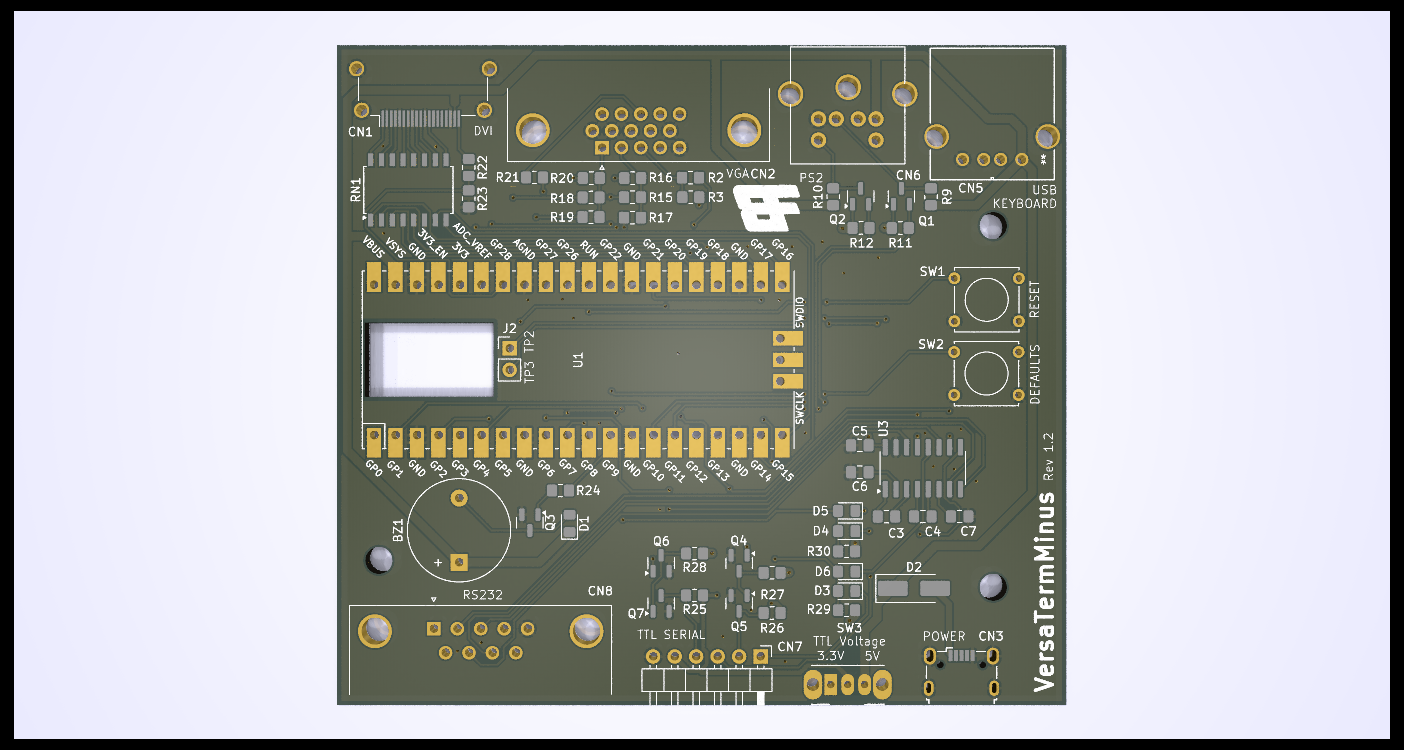
You can order PCBs for this project direct from PCBWay's shared projects (https://www.pcbway.com/project/shareproject/VersaTermMinus_d8ad71ad.html)
There are four significant changes to the board:
The changes allow the board to be reduced in size and cost.
It is highly recommended to use a stencil and hot plate for mounting the SMD components. If assembling by hand, start with the MAX232 chip and resistor pack. It is important to mount the small resistors, capacitors and diodes before adding the HDMI, USB and large through-hole components. Failing to do those first will make assembly much harder.
If you want to use the USB keyboard option a pair of wires needs to be attached to TP2 and TP3 on the underside of the Pico board, and connected to the J2 position on the main board. Pin 1 of J2 should be connected to TP2.
The board uses a regular 0805 footprint for the smaller 1n4148 diodes but it may prove easier to source SOD323. These still fit easily on the 0805 footprint.
The pico board should be loaded with the original VersaTerm firmware from David Hansel's git repository: VersaTerm uf2 firmware
On the first run of the board the traces to the RS232 DE9 connector were incorrect. To fix the error it is necessary to cut three of the traces running from the MAX232 chip to the DE9.
With the DE9 nearest you the top three diagonal traces running from top right to bottom left need to be cut.
Three wires then need soldering to the upper two pins of the DE9 and the lower middle (Pins 2, 3 and 8 of the connector). These need to be wired to the MAX3232 on pins 5, 15 and 16.
DE9 pin 8 -> MAX3232 pin 16
DE9 pin 2 -> MAX3232 pin 5
DE9 pin 3 -> MAX3232 pin 15
To keep the fix tidy I drilled a hold through the PCB above the right hand edge of the DE9 and below the visible traces on the top of the board. This allows shorter, more direct connections to be made.
A second fault exists within the buzzer circuit. The polarity marking for the buzzer is reversed (just fit the buzzer back to front). The transistor switching the buzzer is also incorrect. To fix this the transistor needs rotating around the top left pad (pin 2) such that the top right pin (1) sits on the bottom pad. A wire needs to be run from the now loose pin of the transistor (pin 3) to the negative side of the buzzer, the vacant transistor pad or the top pad of D1. The trace running from transistor to the buzzer could be exposed to allow a solder bridge to be created
| Qty | Value | Footprint | References |
|---|---|---|---|
| 7 | 1K | Resistor_SMD:R_0805_2012Metric_Pad1.20x1.40mm_HandSolder | R3, R16, R19, R27, R28, R29, R30 |
| 7 | 2N7002 | Package_TO_SOT_SMD:SOT-23 | Q1, Q2, Q3, Q4, Q5, Q6, Q7 |
| 5 | 100nF | Capacitor_SMD:C_0805_2012Metric_Pad1.18x1.45mm_HandSolder | C3, C4, C5, C6, C7 |
| 5 | 10K | Resistor_SMD:R_0805_2012Metric_Pad1.20x1.40mm_HandSolder | R9, R10, R11, R12, R23 |
| 5 | 1N4148 | Diode_SMD:D_0805_2012Metric_Pad1.15x1.40mm_HandSolder | D1, D3, D4, D5, D6 |
| 5 | 470R | Resistor_SMD:R_0805_2012Metric_Pad1.20x1.40mm_HandSolder | R2, R17, R20, R25, R26 |
| 3 | MountingHole | MountingHole:MountingHole_3.2mm_M3 | H1, H2, H3 |
| 2 | 100R | Resistor_SMD:R_0805_2012Metric_Pad1.20x1.40mm_HandSolder | R21, R24 |
| 2 | 2K2 | Resistor_SMD:R_0805_2012Metric_Pad1.20x1.40mm_HandSolder | R15, R18 |
| 1 | 270R | Package_SO:SOIC-16W_5.3x10.2mm_P1.27mm | RN1 |
| 1 | 3V3/5V | Button_Switch_THT:SW_Slide_SPDT_Angled_CK_OS102011MA1Q | SW3 |
| 1 | 4K7 | Resistor_SMD:R_0805_2012Metric_Pad1.20x1.40mm_HandSolder | R22 |
| 1 | Buzzer | Buzzer_Beeper:Buzzer_12x9.5RM7.6 | BZ1 |
| 1 | DBA140SL-HF | Diode_SMD:D_SMA_Handsoldering | D2 |
| 1 | DE15_Socket | Connector_Dsub:DSUB-15-HD_Female_Horizontal_P2.29x1.98mm_EdgePinOffset3.03mm_Housed_MountingHolesOffset4.94mm | CN2 |
| 1 | DE9 Socket | Connector_Dsub:DSUB-9_Male_Horizontal_P2.77x2.84mm_EdgePinOffset4.94mm_Housed_MountingHolesOffset7.48mm | CN8 |
| 1 | DEFAULTS | Button_Switch_THT:SW_Tactile_Straight_KSA0Axx1LFTR | SW2 |
| 1 | HDMI_A | Connector_HDMI:HDMI_A_Amphenol_10029449-x01xLF_Horizontal | CN1 |
| 1 | LOGO | Logos:tbs_logo | G*** |
| 1 | LOGO | Logos:BF | G*** |
| 1 | LOGO | Logos:mfmi_logo | G*** |
| 1 | MAX3232 | Package_SO:SOIC-16_3.9x9.9mm_P1.27mm | U3 |
| 1 | Mini-DIN-6 | Connector_Mini_DIN:KMDGX-6S-N | CN6 |
| 1 | RESET | Button_Switch_THT:SW_Tactile_Straight_KSA0Axx1LFTR | SW1 |
| 1 | Raspberry Pi Pico | MCU_RaspberryPi_and_Boards:RPi_Pico_SMD_TH | U1 |
| 1 | TTL Serial | Connector_PinHeader_2.54mm:PinHeader_1x06_P2.54mm_Horizontal | CN7 |
| 1 | USB-A | Connector_USBA_Molex:CONN_67643-2911_MOL | CN5 |
| 1 | USBDATA | Connector_PinHeader_2.54mm:PinHeader_1x02_P2.54mm_Vertical | J2 |
| 1 | USB_B_Micro | Connector_USB:USB_Micro-B_Wuerth_629105150521 | CN3 |
doudar/SmartSpin2k
Transform your spin bike into a Smart Trainer!


zephray/ELTerm
ANSI/VT100-compatible serial terminal built with Raspberry Pi Pico and EL640.480-AM/AG screen


Tjeerdie/SPECTRE
Speeduino compatible engine control unit (ECU) based around black STM32F407VET6 board.

scrapcomputing/ThrottleBlaster
A Turbo circuit with a MHz display that can slow down the CPU speed

cole8888/SRNE-Solar-Charge-Controller-Monitor
Read data from SRNE solar charge controllers.

It measures 86.2 × 78 mm and has 2 copper layers, 1.6 mm thick.
61 parts, built around the MAX3232ID. The full list of its parts is on this page, with links to each part's symbol and footprint where PCBKit's library has them.
From the jimbro1000/VersaTermMinus repository on GitHub, at the commit this page was made from: the board is VersaTermMinus.kicad_pcb and its schematic VersaTermMinus.kicad_sch. PCBKit opens the board in the browser, with nothing to install.
Its repository publishes it under the GPL-3.0 licence: you may reuse it on that licence's terms (keep the author's notice, and for a copyleft licence share your changes alike).