Skip to the content
4 layers50 × 87 mmEnergyMe Home, the printed circuit board in 3D

Smart energy meter capable of monitoring up to 16 channels. Supports MQTT, REST API, Modbus TCP, InfluxDB, AWS IoT Core. Friendly UI and fully open source (PCB, schematics, components, source code)

Size
50 × 87 mm
Copper layers
4
Thickness
1.6 mm
Parts
87
Nets
60
Pads
315
Tracks, vias
578, 248
Pours
39
Routed
Yes
KiCad
KiCad 10.0 (file 20260206)
Created
19 Apr 2024
Updated
5 Nov 2026

Overview

EnergyMe Home is an open-source printed circuit board by jibrilsharafi, from the jibrilsharafi/EnergyMe-Home repository on GitHub, published under the GPL-3.0 licence. It is a 4-layer board of 50 × 87 mm with 87 parts on 60 nets, routed with 578 tracks and 248 vias.

It is built around the HLK-PM03, ZX-QC66-7.5TP and 74HC4067PW,118-JSM, with the ADE7953ACPZ-RL, DB301V-5.0-2P-BU-S and PJ-3200 among its other parts. Its parts include 25 capacitors, 20 resistors, 8 connectors, 7 ICs and 1 diode. It belongs with the home automation and IoT boards and the ESP32 boards of this library.

Main components

12

README

README.md

EnergyMe-Home

Coverage

🛒 Want it ready to use? Pre-assembled and calibrated units. Just install and monitor!

Available on our website and on Tindie

Release Stars License OSHWA Certified Open Source Hardware IT000025

Homepage

EnergyMe-Home is an open-source energy monitoring system for home use, capable of monitoring up to 16 circuits. It integrates with any platform through REST API, MQTT, Modbus TCP, and InfluxDB.

Built for makers and DIY enthusiasts who want to track their home's energy consumption. The hardware uses ESP32-S3 and ADE7953 energy measurement IC, while the firmware is written in C++ with PlatformIO and Arduino framework. You can build and customize it yourself - all hardware designs and software are open-source. Prefer it ready to go? Grab a pre-assembled unit.

A demo speaks more than 1000 words: try the demo dashboard!

Join the community! Head over to GitHub Discussions - ask questions, share your builds and dashboards, suggest features, and exchange integration tips. It's the home for everyone building, installing, or tinkering with EnergyMe-Home

Supported Electrical Systems

EnergyMe-Home is compatible with various electrical systems worldwide:

System TypeVoltageConfigurationSupported
Single Phase230VL + N✅ Europe, Asia, Africa, Oceania
Split Phase120V/240VL1 + L2 + N✅ North America residential
Split Phase120V/240VL1 + L2 (no N)✅ Old electrical systems
Three Phase400V/230V3L + N❕ Europe commercial/industrial (derived voltages)
Three Phase208V/120V3L + N❕ North America commercial (derived voltages)

Current Transformers Supported:

  • 333 mV output CTs (+- 500 mV absolute)
  • 3.5 mm jack connectors for easy plug-and-play

Monitoring Capacity:

  • Up to 16 circuits simultaneously
  • 1× main circuit, sampled at high frequency for accurate total energy measurement
  • 15× branch circuits, multiplexed for individual monitoring

⚠️ Important: Installation requires working with your main electrical panel. Always consult a qualified electrician if you're not experienced with electrical installations. The user is responsible for ensuring compliance with local electrical codes and regulations, and assumes all risks associated with the installation and use of this device.

Hardware
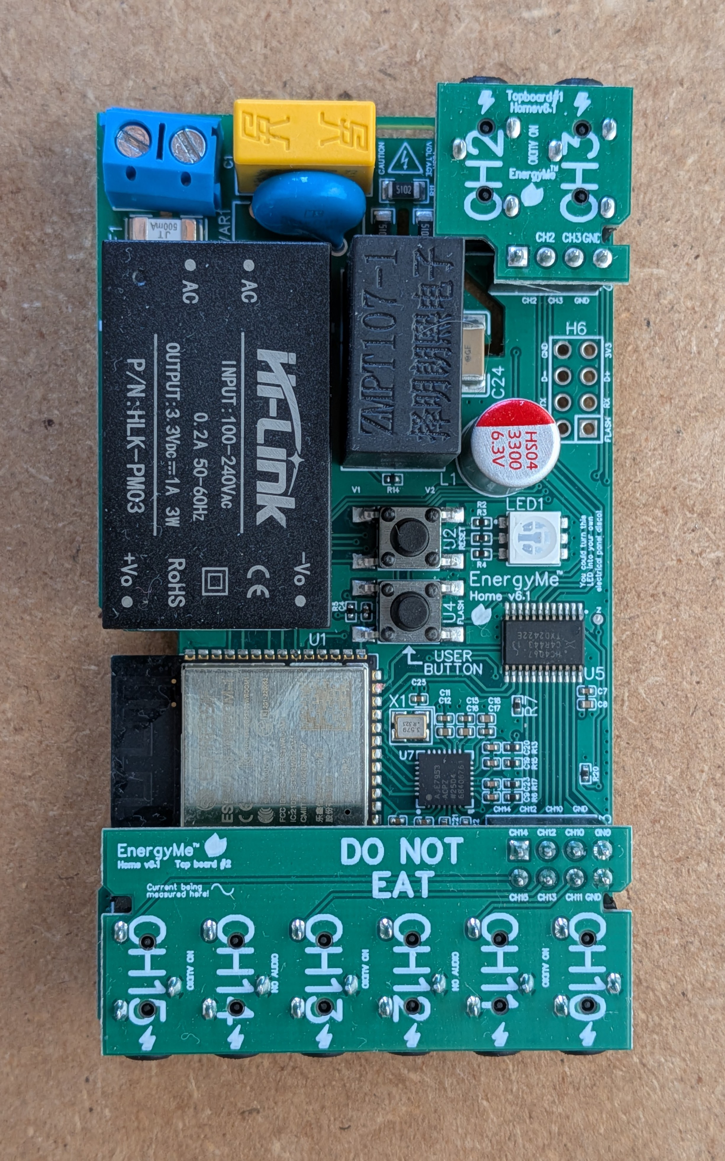
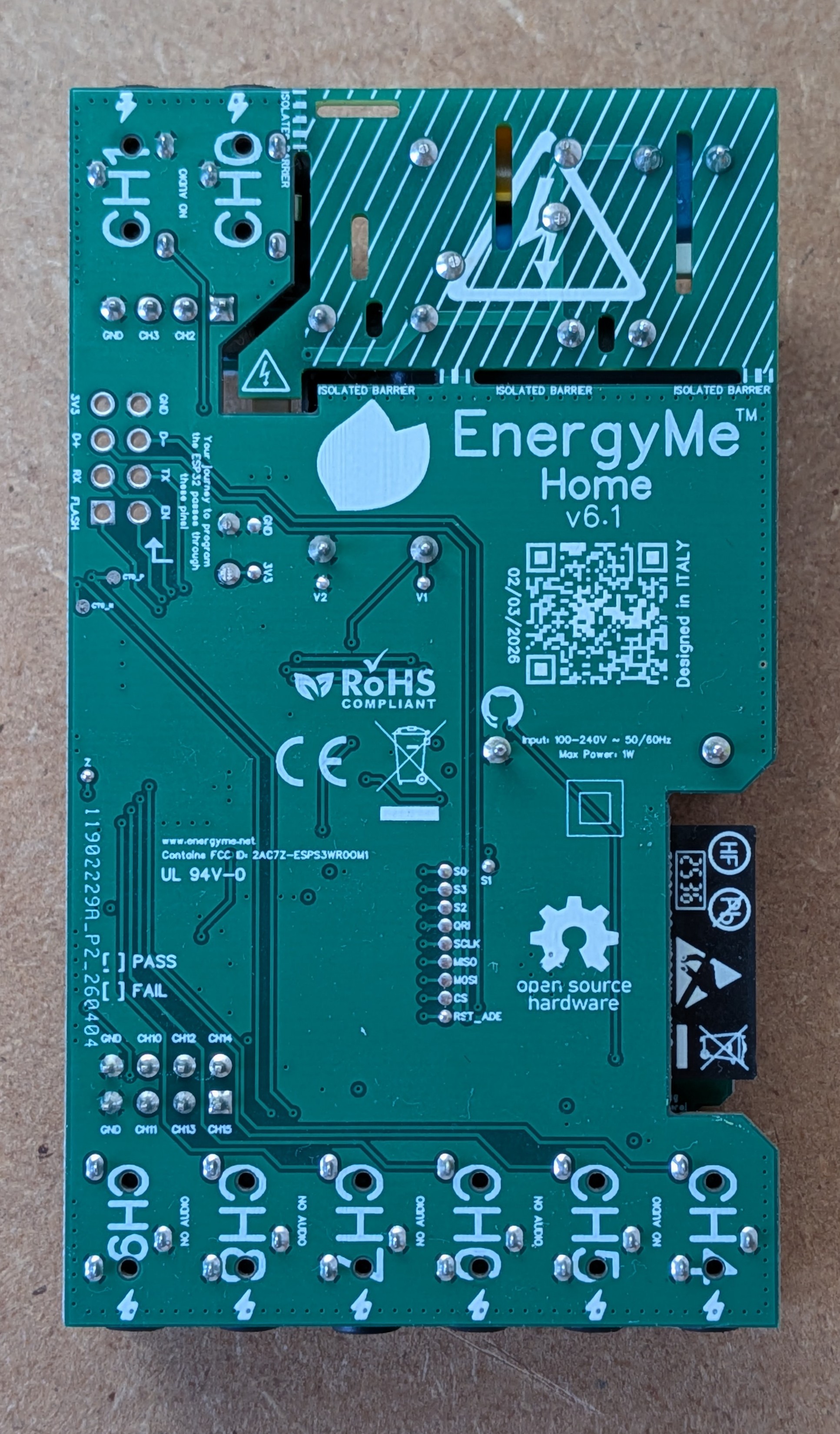
PCB front PCB back

The hardware (currently at v6.1) consists of both the PCB design and the components used to build the energy monitoring system.

The key components include:

  • ESP32-S3: the brain of the project
  • ADE7953: single-phase energy measurement IC
  • ZMPT107-1: voltage transformer providing full galvanic isolation between the AC mains and the low-voltage measurement circuitry, with no direct connection between mains and the board's ground
  • Multiplexers: used to monitor multiple circuits at once
  • 3.5 mm jack connectors: used to easily connect current transformers

PCB schematics and BOMs are available in the hardware/pcb directory, while datasheets for key components are in the hardware/components directory. Additional hardware specifications and technical details can be found in the hardware/README.md, with a condensed one-page summary in the PCB & Firmware Datasheet.

The project is published on EasyEDA for easy access to the PCB design files. You can find the project on EasyEDA OSHWLab.

Software

The firmware is built with C++ using the PlatformIO ecosystem and Arduino 3.x framework, with a task-based architecture using FreeRTOS.

Key Features:

  • Energy Monitoring: ADE7953 driver with energy accumulation and CSV logging
  • Channel Roles: Load, grid, PV, battery, hybrid inverter and bidirectional channels, with automatic CT reversal detection
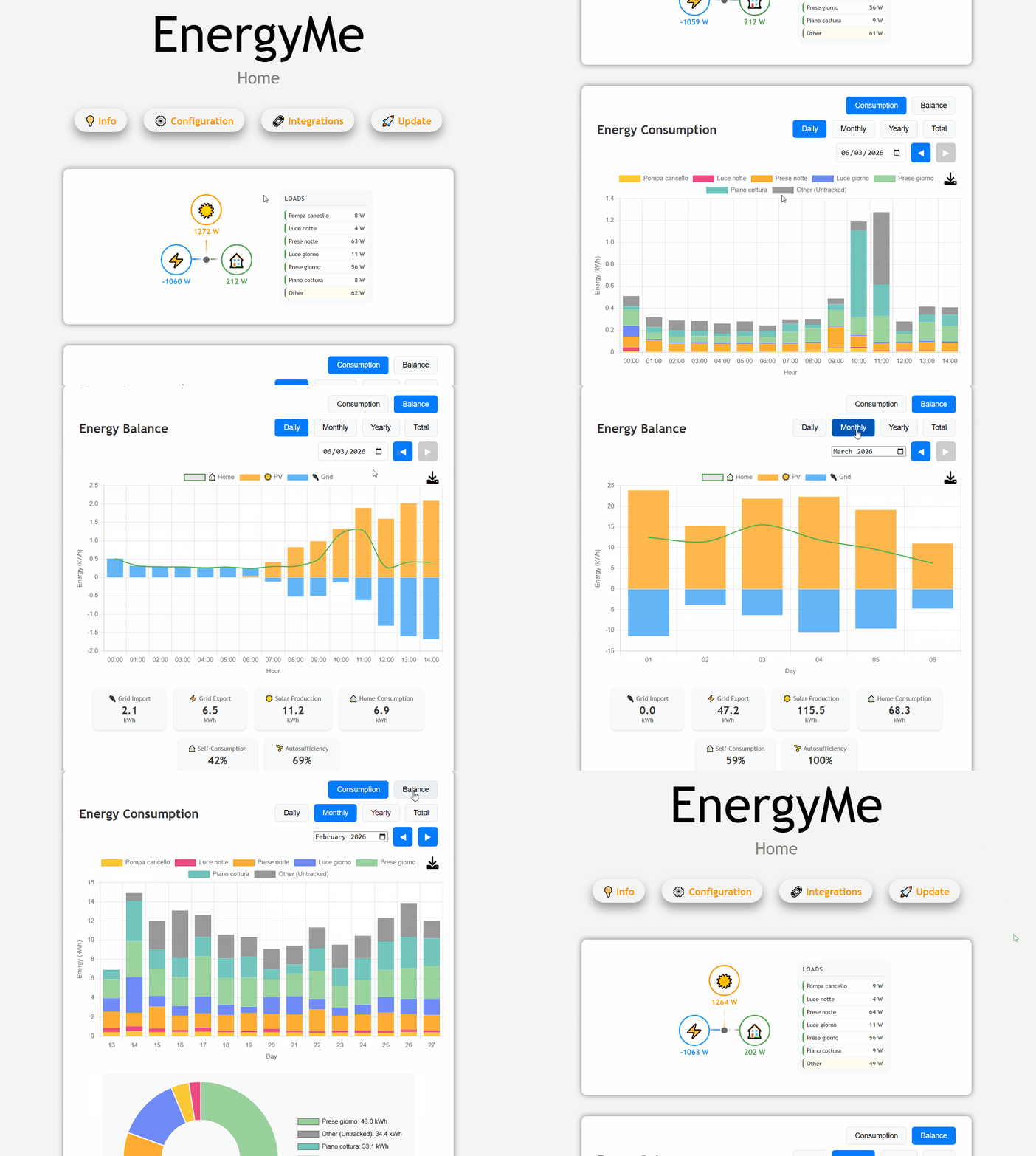
  • Web Interface: Dashboard for monitoring and system configuration
  • Authentication: HTTP Digest with forced default-password change and brute-force lockout
  • Integration Options: REST API, MQTT, InfluxDB, and Modbus TCP
  • Crash Recovery: Automatic recovery, firmware rollback and core dump archive
  • WiFi Setup: Captive portal for configuration and mDNS support (energyme.local)
  • OTA Updates: Firmware updates with MD5 verification and rollback (cloud updates are signature-verified)
  • Device Health: Issue registry (CT polarity, over-temperature, ...) and grid blackout detection
  • Waveform Analyzer: Capture high-resolution voltage & current waveforms per channel from the web UI

For detailed architecture, implementation details, and API documentation, see source/README.md.

Integration

EnergyMe-Home offers multiple integration options:

  • REST API: Complete Swagger-documented API for all data and configuration (swagger.yaml)
  • MQTT: Publish energy data to any MQTT broker with optional authentication
  • Modbus TCP: Industrial protocol for SCADA systems integration
  • InfluxDB: Support for both v1.x and v2.x with SSL/TLS and buffering
  • Home Assistant: Dedicated custom integration (homeassistant-energyme)

For detailed integration guides and implementation details, see the source README.

Home Assistant Integration

EnergyMe-Home integrates with Home Assistant through a dedicated custom integration.
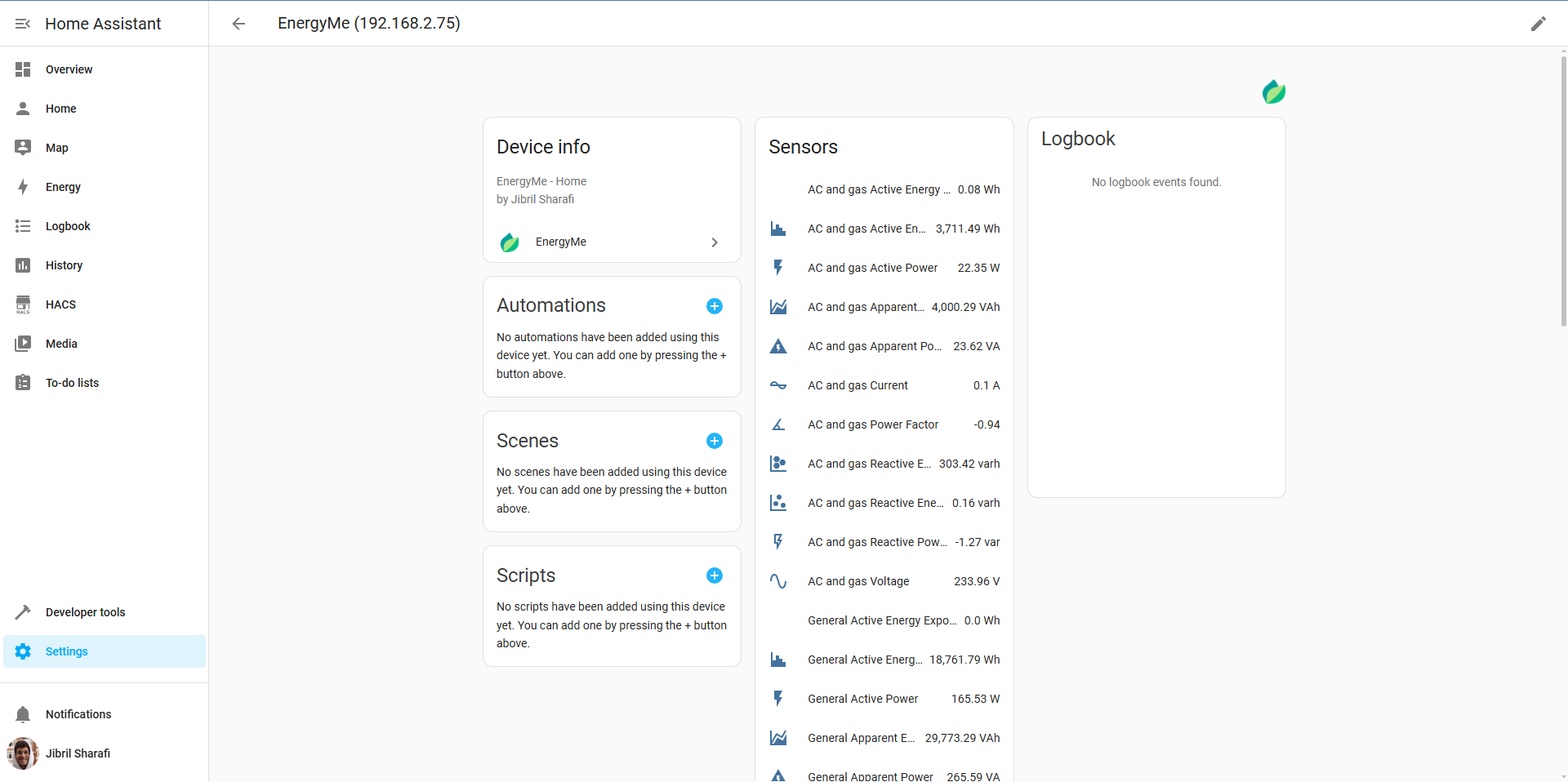
Home Assistant Integration

  • Setup: Requires device IP address (automatic discovery via mDNS coming soon)
  • Data: All energy measurements and system information as Home Assistant entities
  • Access: Monitor all circuits and aggregate data within Home Assistant

Get started at homeassistant-energyme.

Getting Started

  1. Order the PCB: Download the design files from the Schematics folder and order from your preferred PCB manufacturer
  2. Populate the board: Solder all components using the BOMs in hardware/pcb/main_board/, hardware/pcb/top_board_1/, and hardware/pcb/top_board_2/
  3. Flash the firmware: Connect a USB-to-UART adapter to the UART pins and flash using PlatformIO
  4. Configure WiFi: Power on the device and connect to the captive portal to set up WiFi credentials
  5. Start monitoring: Access the web interface at http://energyme.local (default credentials: admin/energyme, you will be asked to change the password at first login)

For detailed build instructions and troubleshooting, see the manual.

Privacy & Telemetry

Optional anonymous usage statistics sent once per boot: hashed device ID, firmware version, country/city (from public IP). Helps count active installations. No personal data or usage patterns collected. Disable in platformio.ini: set ENABLE_OPEN_SOURCE_TELEMETRY=0.

Releases

Firmware binaries and per-version release notes are published on GitHub Releases. See CHANGELOG.md for an index of versions and links to the corresponding pull requests.

Contributing

Contributions are welcome! Please read the contributing guidelines for more information.

License

This project contains both software and hardware components:

See the respective license files for full details.

Parts

87
QtyValueFootprintReferences
9100nFC0402C4, C5, C7, C10, C11, C13, C15, C17, C25
91kΩR0402R2, R3, R4, R6, R9, R13, R15, R16, R17
8PJ-3200AUDIO-TH_PJ-3200CN1, CN2, CN6, CN7, CN8, CN9, CN10, CN11
710uFC0402C3, C6, C8, C12, C14, C16, C18
633nFC0402C9, C19, C20, C21, C22, C23
410kΩR0402R1, R5, R7, R8
31MΩR0402R18, R19, R20
351kΩR1206R10, R11, R12
2ZX-QC66-7.5TPKEY-SMD_4P-L6.0-W6.0-P4.50-LS8.6U2, U4
1100nFCAP-TH_L13.0-W6.0-P10.00-D1.0C1
1180ΩR0402R14
11nFC2211C24
13.579545MHzOSC-SMD_4P-L3.2-W2.5-BL_FT3HNBPK16.0-T1X1
13300uFCAP-TH_BD8.0-P3.50-D0.6-FDC2
1561KD10RES-TH_L12.5-W4.8-P7.50-D1.2-S3.40VAR1
174HC4067PW,118TSSOP-24_L7.8-W4.4-P0.65-LS6.4-BLU5
1ADE7953ACPZ-RLLFCSP-28_L5.0-W5.0-P0.50-BL-EPU7
1DB301V-5.0-2PCONN-TH_2P-P5.00_L7.6-W10.0U6
1ESP32-S3-WROOM-1(N16R2)WIRELM-SMD_ESP32-S3-WROOM-1U3
1HLK-PM03PWRM-TH_HLK-PM03U1
1JFC2410-0500TSF2410F1
1PM254V-11-04-H85HDR-TH_4P-P2.54-V-FH2
1PM254V-12-08-H85_C2834799HDR-TH_8P-P2.54-V-F-R2-C4-S2.54H3
1PZ254V-12-8PHDR-TH_8P-P2.54-V-M-R2-C4-S2.54H6
1Pad_gge151921Pad_gge151921Pad_gge151921
1Pad_gge152239Pad_gge152239Pad_gge152239
1Pad_gge152290Pad_gge152290Pad_gge152290
1Pad_gge152317Pad_gge152317Pad_gge152317
1Pad_gge152344Pad_gge152344Pad_gge152344
1Pad_gge152371Pad_gge152371Pad_gge152371
1Pad_gge152398Pad_gge152398Pad_gge152398
1Pad_gge152517Pad_gge152517Pad_gge152517
1Pad_gge153190Pad_gge153190Pad_gge153190
1Pad_gge153217Pad_gge153217Pad_gge153217
1Pad_gge153244Pad_gge153244Pad_gge153244
1Pad_gge153271Pad_gge153271Pad_gge153271
1Pad_gge157644Pad_gge157644Pad_gge157644
1Pad_gge157767Pad_gge157767Pad_gge157767
1Pad_gge157888Pad_gge157888Pad_gge157888
1Pad_gge165863Pad_gge165863Pad_gge165863
1Pad_gge165890Pad_gge165890Pad_gge165890
1Pad_gge166044Pad_gge166044Pad_gge166044
1Pad_gge166065Pad_gge166065Pad_gge166065
1TC5050RGBF08-3CJH-AF53ALED-SMD_6P-L5.0-W5.0-TL_TC5050RGBF08LED1
1ZMPT107-1XFMR-TH_ZMPT107-1L1

More from jibrilsharafi/EnergyMe-Home

2
  • 2 layers47.8 × 20.3 mmTop board 2, the printed circuit board in 3D

    Top board 2

    jibrilsharafi/EnergyMe-Home

    Smart energy meter capable of monitoring up to 16 channels. Supports MQTT, REST API, Modbus TCP, InfluxDB, AWS IoT Core. Friendly UI and fully open source (PCB, schematics, components, source code)

    7 parts288GPL-3.0
  • 2 layers17.8 × 17.8 mmTop board 1, the printed circuit board in 3D

    Top board 1

    jibrilsharafi/EnergyMe-Home

    Smart energy meter capable of monitoring up to 16 channels. Supports MQTT, REST API, Modbus TCP, InfluxDB, AWS IoT Core. Friendly UI and fully open source (PCB, schematics, components, source code)

    3 parts288GPL-3.0

Similar boards

  • 4 layers180 × 120 mmMG ZS V2, the printed circuit board in 3D

    MG ZS V2

    damienmaguire/MG-EV-Inverter

    Reverse engineering of the drive motor and inverter used in MG Electric Vehicles

    177 parts17GPL-3.0
  • 4 layers117.6 × 83 mmNile test chip pcb, the printed circuit board in 3D

    Nile test chip pcb

    Ash-tronix/nile_test_chip_pcb

    KiCad PCB design files to support the Ashtronix® Nile test chip.

    177 parts
  • 2 layers64 × 50 mmEverAliveSensor PCB, the printed circuit board in 3D

    EverAliveSensor PCB

    jfm92/everAliveSensor

    Solar-powered BLE environmental sensor (temp, humidity, pressure) with a 50F supercapacitor — potentially infinite lifetime, 19-day dark autonomy. ESP32 + BME680. Experimental.

    54 parts28
  • 4 layers67 × 86 mmEnergymeter, the printed circuit board in 3D

    Energymeter

    jimmyw/energymeter

    122 parts5
  • 2 layers98.8 × 85.2 mmHub, the printed circuit board in 3D

    Hub

    maxime-leblan/Projet-VigiZone-E3-2026-ESIEE-Paris

    VigiZone est un système de prévention anti-collision entre engins et piétons dans le BTP. Réalisé dans le cadre de notre projet de fin d'année en 1ère année du cycle ingénieur à ESIEE Paris.

    34 parts2BSD-2-Clause
  • 2 layers125.5 × 79 mmPeterThePowerMeter, the printed circuit board in 3D

    PeterThePowerMeter

    CtrlAltJon/PeterThePowerMeter

    IoT Power Meter for real-time energy monitoring. Includes a local color display, acoustic alarms, and a web interface for smart home integration (Home Assistant/MQTT).

    79 parts1MIT
  • 2 layers128 × 58.8 mmSensor energia bl0940, the printed circuit board in 3D

    Sensor energia bl0940

    alejomancinelli/FCEIA_ProyectoFinal

    Proyecto Final de Ing. Electrónica: Sistema de monitoreo de red eléctrica doméstica y/o industrial

    44 parts
  • 2 layers44 × 85 mmNano IPBL 2026, the printed circuit board in 3D

    Nano IPBL 2026

    Decr0zeath/ipbl2026-quadruped-robot

    A KiCad-based PCB design for servo motor control in a quadruped robot developed for the International Project Based Learning (iPBL) 2026 program.

    20 parts

Questions

How big is the EnergyMe Home PCB?

It measures 50 × 87 mm and has 4 copper layers, 1.6 mm thick.

What parts does the EnergyMe Home use?

87 parts, built around the HLK-PM03, ZX-QC66-7.5TP, 74HC4067PW,118-JSM and ADE7953ACPZ-RL. The full list of its parts is on this page, with links to each part's symbol and footprint where PCBKit's library has them.

Where can I download the EnergyMe Home KiCad files?

From the jibrilsharafi/EnergyMe-Home repository on GitHub, at the commit this page was made from: the board is hardware/pcb/kicad/main_board/main_board.kicad_pcb. PCBKit opens the board in the browser, with nothing to install.

Can I use the EnergyMe Home design in my own project?

Its repository publishes it under the GPL-3.0 licence: you may reuse it on that licence's terms (keep the author's notice, and for a copyleft licence share your changes alike).