2 layers60 × 30 mm
Controller
google/mozc-devices
Circuit diagrams and firmware source code for Gboard DIY keyboards
11 parts3kApache-2.0

 JH-2108/Macropad
I am building a macropad with an OLED screen, this macropad allows me to play games on it while also opening certain applications or conduct specific commands on my laptop.
Macropad is an open-source printed circuit board by JH-2108, from the JH-2108/Macropad repository on GitHub, published under the MIT licence. It is a 2-layer board of 99 × 74.5 mm with 11 parts on 13 nets, routed with 83 tracks and 0 vias.
Its parts include 9 switches, 1 IC and 1 connector. It belongs with the keyboards and input and lEDs and displays boards of this library.
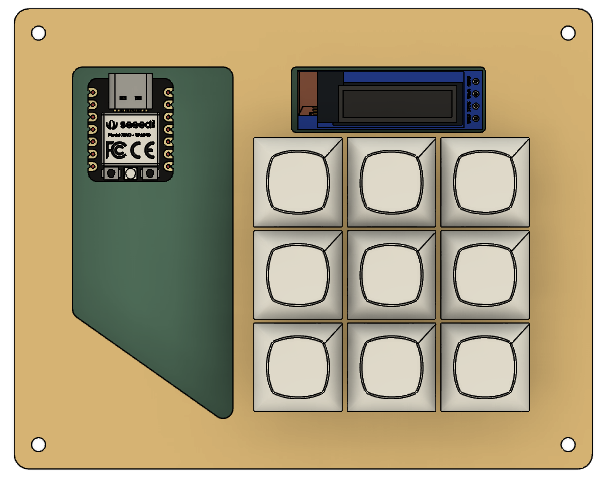
A custom 9-key macropad built from scratch using KiCad, featuring a Seeed Studio XIAO microcontroller and a 0.91" OLED display.
My Overall Hackpad
Schematics
PCB Design
Connecting the Case and PCB
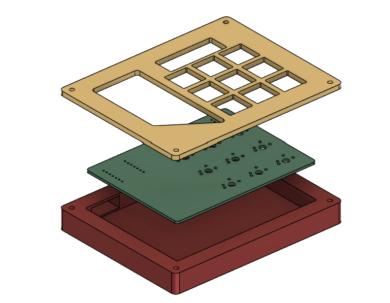
During the entire design process, I did not face as many challenges as one would being a beginner to creating a Hackpad, before I started this project, I already had the basic understanding of how Fusion360 works, the only thing I needed to master and know are how to created the PCB and the firmware for my Hackpad to successfully function. In order to solve this issue, I went online; searched for tutorials, asked my friend who has a deep sense of love in coding and programming; through these resources, I was able to fully finish designing my Hackpad. For beginners reading this, I believe that you are able to make one too, just like I did!!!
This is everything that you should prepare in order to make this Hackpad
| Component | Quantity |
|---|---|
| Seeed Studio XIAO | 1 |
| Mechanical key switches | 9 |
| Keycaps | 9 |
| 0.91" OLED display | 1 |
| Custom PCB | 1 |
| USB-C connection | 1 |
macropad/
├── README.md
├── PCB/
│   ├── macropad.kicad_pro
│   ├── macropad.kicad_sch
│   ├── macropad.kicad_pcb
├── CAD files/
│   ├─ base
│   ├─ plate
├── images/
└── LICENSEThe firmware will control the macropad's keys and OLED display.
Planned functionality includes:
This project is open source. See the LICENSE file for details.
Designed and built by JH as a personal hardware and electronics project(and tool)!
If you find this project interesting, feel free to take inspiration from it!!! :)
| Qty | Value | Footprint | References |
|---|---|---|---|
| 9 | SW_Push | Button_Switch_Keyboard:SW_Cherry_MX_1.00u_PCB | SW1, SW2, SW3, SW4, SW5, SW6, SW7, SW8, SW9 |
| 1 | Conn_01x04 | Footprint:SSD1306-0.91-OLED-4pin-128x32 | J1 |
| 1 | MOUDLE-SEEEDUINO-XIAO | Footprint:XIAO-Generic-Hybrid-14P-2.54-21X17.8MM | U1 |
It measures 99 × 74.5 mm and has 2 copper layers, 1.6 mm thick.
11 parts. The full list of its parts is on this page, with links to each part's symbol and footprint where PCBKit's library has them.
From the JH-2108/Macropad repository on GitHub, at the commit this page was made from: the board is PCB/Macropad.kicad_pcb and its schematic PCB/Macropad.kicad_sch. PCBKit opens the board in the browser, with nothing to install.
Its repository publishes it under the MIT licence: you may reuse it on that licence's terms (keep the author's notice, and for a copyleft licence share your changes alike).
google/mozc-devices
Circuit diagrams and firmware source code for Gboard DIY keyboards


FrameworkComputer/ExpansionCards
Reference designs and documentation to create Expansion Cards for the Framework Laptop

hoglet67/RGBtoHDMI
Bare-metal Raspberry Pi project that provides pixel-perfect sampling of Retro Computer RGB/YUV video and conversion to HDMI

hackclub/OnBoard
💡 Join 1,000 teenagers and make your first PCB with a $100 grant!


tardate/LittleArduinoProjects
a collection of "Little Electronic & Arduino Projects", most involving electronics or an Arduino in one way or another!

basilfx/TRADFRI-Hacking
Hacking IKEA TRÅDFRI products, such as light bulbs, window blinds and other accessories.