4 layers120 × 120 mm

 jduanen/Acoustic-Camera20
Low-cost, High-performance, Acoustic Camera
Mic array is an open-source printed circuit board by jduanen, from the jduanen/Acoustic-Camera repository on GitHub, published under the MIT licence. It is a 4-layer board of 320 × 320 mm with 321 parts on 182 nets, routed with 5,287 tracks and 679 vias.
It is built around the LMK1C1108PW, CDCLVC1112PW and IM72D128V01XTMA1, with the MCP1700T-3302E/TT(MS), ASFL1-12.288MHZ-L-T and AXK6S80637YG among its other parts. Its parts include 182 capacitors, 109 ICs, 14 resistors, 1 connector and 1 crystal.


This project involves the design and implementation of a low-cost, high-performance acoustic camera: i.e., a microphone array computes a power map of the sound sources in a video camera's field of view and overlays it on the video in real time.
Uses of such a device include locating vibration, gas leaks and electrical breakdown, and as a hearing aid for people who can no longer localize sound with one functional ear.
One of the top-level objectives for this project is to explore the use of deep-learning models for this application and compare the performance and cost with that of traditional DSP-based beamforming algorithms.
A full technical overview of the project can be found in OVERVIEW.md; see the linked documents for more detail.
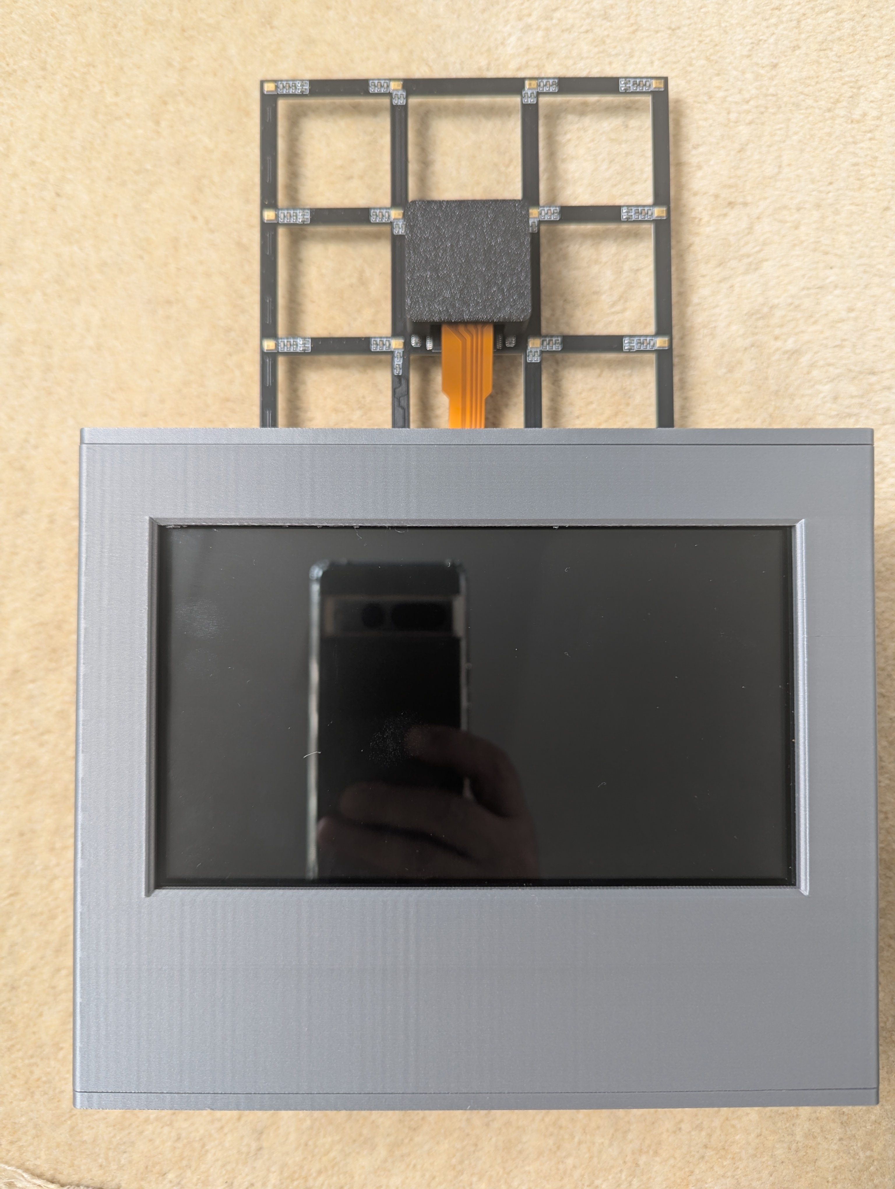
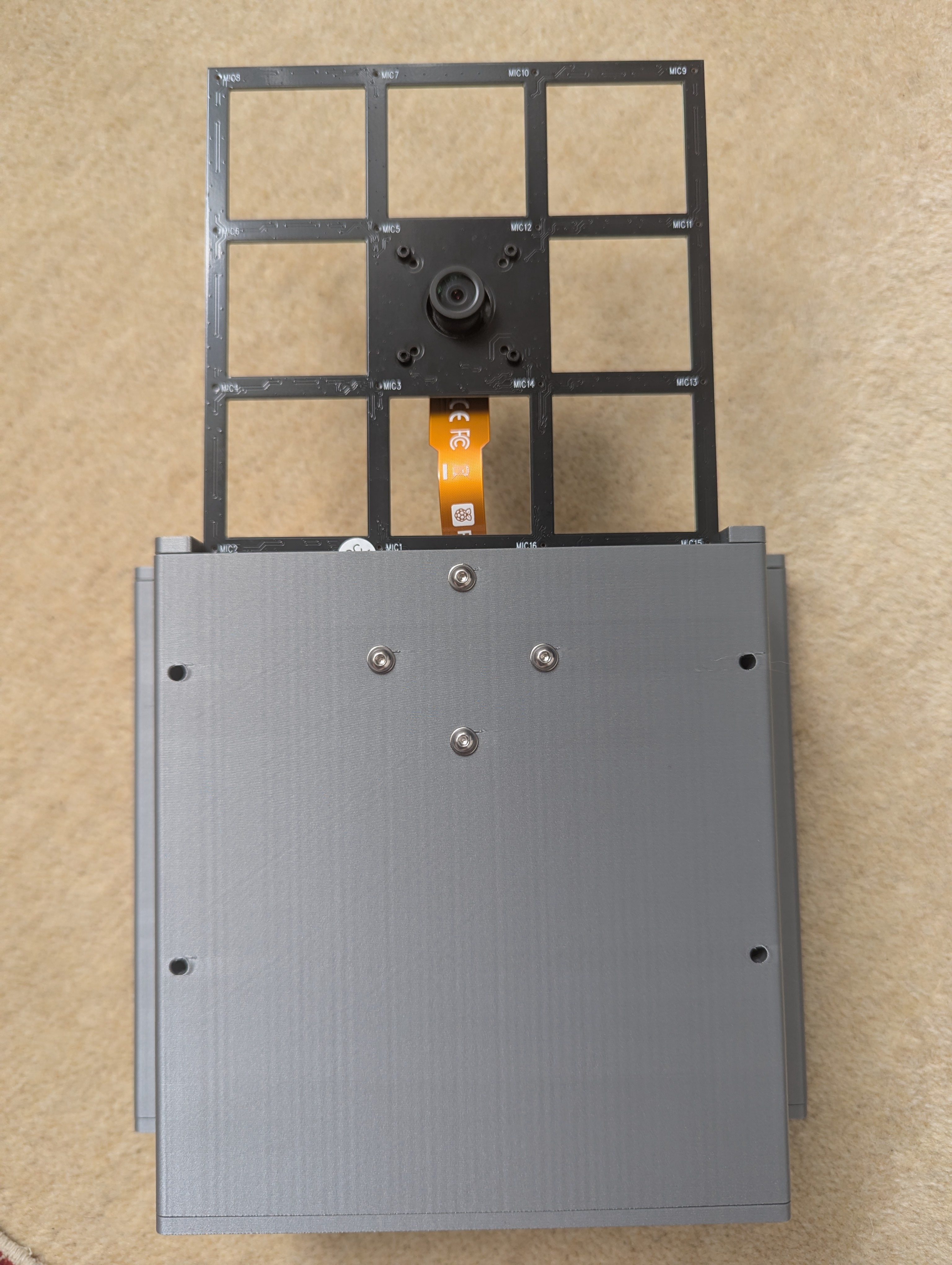
The Phase 3 prototype (4x4-mic array) unit looks like this:
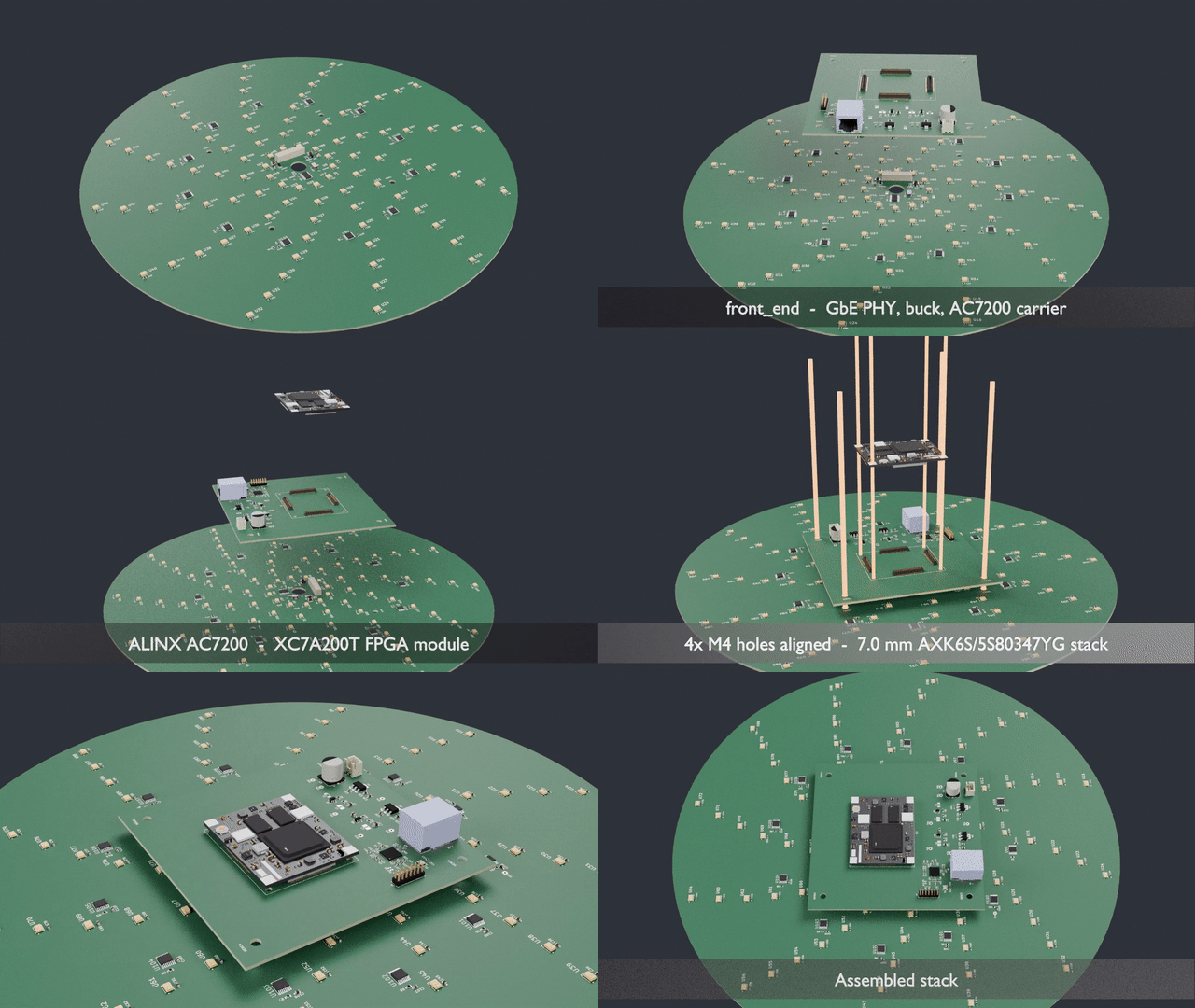
This is an animation of the current state of the Phase 4 (96-mic spiral array) version's PCBs:
See an example of a commercial product here Fluke and a low-cost consumer product here Fotric
The microphone array samples the sound field at every mic at once. For each candidate direction (azimuth, elevation), a steering vector describes the expected phase pattern across the mics; a beamformer scores each direction against the measured cross-spectral matrix (CSM) and the scores form the energy map overlaid on the video.
Three array properties set performance:
| Property | Controls | Rule |
|---|---|---|
| Aperture D | Beam width (resolution) and low-frequency limit | HPBW ≈ 58° × λ/D; useful directionality needs f > c/D |
| Minimum mic spacing d | High-frequency limit (grating lobes above it) | fNyq = c / (2d) |
| Mic layout and count | Sidelobe level (MSL), SNR | Irregular spacing suppresses aliasing; more mics lower sidelobes |
Other key ideas: far field begins at r > 2D²/λ; the point spread function is how the array smears a point source; commercial cameras average power incoherently across an octave band to cut noise. Details: BACKGROUND.md, MIC_ARRAYS.md.
Algorithms explored (one per family): Delay-and-Sum (simple, robust, wide beam), MVDR (adaptive, suppresses interferers), CLEAN-SC (deconvolution, removes PSF artifacts), MUSIC (subspace, super-resolution when the source count is known). ML methods come in Phase 5.
| Parameter | Target |
|---|---|
| Frequency range | 200 Hz: 8 kHz (useful imaging from ~2 kHz) |
| Resolution (HPBW) | ~9.4° @ 8 kHz, ~19° @ 4 kHz, ~82° @ 1 kHz (simulated, Phase 4 array) |
| Distance | ~0.5 m (far-field limit) to ~10 m |
| Field of view | ±45° H, ±30° V, matched to the camera |
| Array | ~300 mm aperture, 96 MEMS mics, Underbrink 12 × 8 log-spiral, 12.94 mm min spacing (Nyquist ≈ 13.3 kHz) |
Why these numbers (TRADEOFFS.md):
Each phase delivers a working end-to-end system (PLAN.md).
| Phase | Hardware | Goal | Status |
|---|---|---|---|
| 1 | Simulation | Validate algorithms and array geometry | Complete |
| 2 | ReSpeaker XVF3800 (4 mics, 90 mm) | First end-to-end pipeline: capture → beamform → overlay | Complete |
| 3 | miniDSP UMA-16 v2 (16 mics, 126 mm) | 2D (az × el) beamforming, calibration, touch UI | Complete |
| 4 | Custom PCBs (96 mics, 300 mm, FPGA) | Full-performance system | In progress |
| 5 | Phase 3/4 hardware | ML beamformer (PILOT / CRNN) vs CLEAN-SC | Not started |
src/acoustic_camera_p2.py.src/acoustic_camera_p3.py with a touch UI: frequency sliders and spectrum
pan, energy threshold (auto/manual), zoom/recenter/dwell, power indicator, saved settings.src/beamforming.py (pytest suite in tests/); src/benchmark_algos.py
measures per-algorithm cost. A 1°/pt grid brings all four algorithms within 20 fps.96-mic Underbrink spiral, 12 arms × 8 mics, with PDM → CIC/FIR decimation in an FPGA and data streamed to a host (96 ch × 48 kHz × 24 bit ≈ 110 Mbit/s, within 1 GbE). A Pi Camera Module 3 Wide mounts through the centre of the array.
mic_array: Ø320 mm, 96 Infineon IM72D128 mics, TCXO and clock tree, local 3.3 V LDOs.front_end: AC7200 module, power regulation, DP83867 GbE PHY.Needs real Phase 3/4 data to train and validate models.
| Qty | Value | Footprint | References |
|---|---|---|---|
| 176 | 100nF | Capacitor_SMD:C_0603_1608Metric | C1, C10, C11, C105, C106, C107, C108, C109, C110, C111, C112, C113, C114, C115, C116, C117 +160 |
| 96 | IM72D128V01XTMA1 | IM72D128:IFX-PG-LLGA-5-4 | U1, U2, U10, U11, U12, U13, U14, U15, U16, U17, U18, U19, U20, U21, U22, U23 +80 |
| 13 | 10k | PCM_SparkFun-Resistor:R_0603_1608Metric | R1, R2, R3, R4, R5, R6, R7, R8, R9, R10, R11, R12, R13 |
| 12 | LMK1C1108PW | CDCLVC1108:PW0016A_N | U97, U98, U99, U100, U101, U102, U103, U104, U105, U106, U107, U108 |
| 4 | 1uF | Capacitor_SMD:C_1206_3216Metric | C98, C99, C100, C101 |
| 4 | MountingHole_2.2mm_M2 | MountingHole_2.2mm_M2 | HCAM1, HCAM2, HCAM3, HCAM4 |
| 4 | MountingHole_4.3mm_M4 | MountingHole_4.3mm_M4 | HENC1, HENC2, HENC3, HENC4 |
| 2 | 100nF | Capacitor_SMD:C_0402_1005Metric | C184, C185 |
| 2 | MCP1700T-3302E/TT | Package_TO_SOT_SMD:SOT-23 | VR1, VR2 |
| 1 | 33 | PCM_SparkFun-Resistor:R_0603_1608Metric | R15 |
| 1 | 3V6 | TestPoint:TestPoint_THTPad_D2.0mm_Drill1.0mm | TP3 |
| 1 | ASFL1-12.288MHZ | Oscillator:Oscillator_SMD_SeikoEpson_SG8002LB-4Pin_5.0x3.2mm | Y1 |
| 1 | AXK6S80637YG | AXK6S80637YG:AXK6S80637YG | J1 |
| 1 | CDCLVC1112PW | CDCLVC1112:PW24 | U110 |
| 1 | CLK 3V3 | TestPoint:TestPoint_THTPad_D2.0mm_Drill1.0mm | TP4 |
| 1 | GND | TestPoint:TestPoint_THTPad_D2.0mm_Drill1.0mm | TP1 |
| 1 | MIC 3V3 | TestPoint:TestPoint_THTPad_D2.0mm_Drill1.0mm | TP2 |
It measures 320 × 320 mm and has 4 copper layers, 1.6 mm thick.
321 parts, built around the LMK1C1108PW, CDCLVC1112PW, IM72D128V01XTMA1 and MCP1700T-3302E/TT(MS). The full list of its parts is on this page, with links to each part's symbol and footprint where PCBKit's library has them.
From the jduanen/Acoustic-Camera repository on GitHub, at the commit this page was made from: the board is pcb/single_fpga/mic_array.kicad_pcb and its schematic pcb/mic_array/arm_00.kicad_sch. PCBKit opens the board in the browser, with nothing to install.
Its repository publishes it under the MIT licence: you may reuse it on that licence's terms (keep the author's notice, and for a copyleft licence share your changes alike).


ccc909/Whistler
Open-source 16-channel USB MEMS microphone array: KiCad PCB design, XMOS XU316 (xcore.ai) USB Audio Class 2 firmware with DFU, BOM and JLCPCB-ready production files. CERN-OHL-S.

spawnID0001/allpeople-wave-pcb
This repository will contain all the pcb design files for the wave product.

antonavhmx/AAM-PCB-
Este repositorio contiene el diseño de hardware y los archivos de manufactura industrial para una tarjeta de circuito impreso de 4 capas.

pierrechevalier83/ferris
A low profile split keyboard designed to satisfy one single use case elegantly

uCAN-LIN/LinUSBConverter
Open source USB ↔ LIN bus dongle. LIN 2.1 master / slave / monitor, optically isolated, SLCAN compatible — no proprietary drivers.


96boards/mezzanine-community
Repository for community designed mezzanine boards for the 96boards specification.