2 layers181.4 × 179.8 mm
Rubber duckey
ajvizganapathy-pixel/FlipperZero-DIY-STM32WB55-NucleusDark
DIY Flipper Zero clone using STM32WB55CGU6 — KiCad PCB, Momentum firmware, 200+ apps, BadUSB scripts, wiring diagrams
37 parts10

 JBlitzar/flopper-one5
esp knockoff flipper
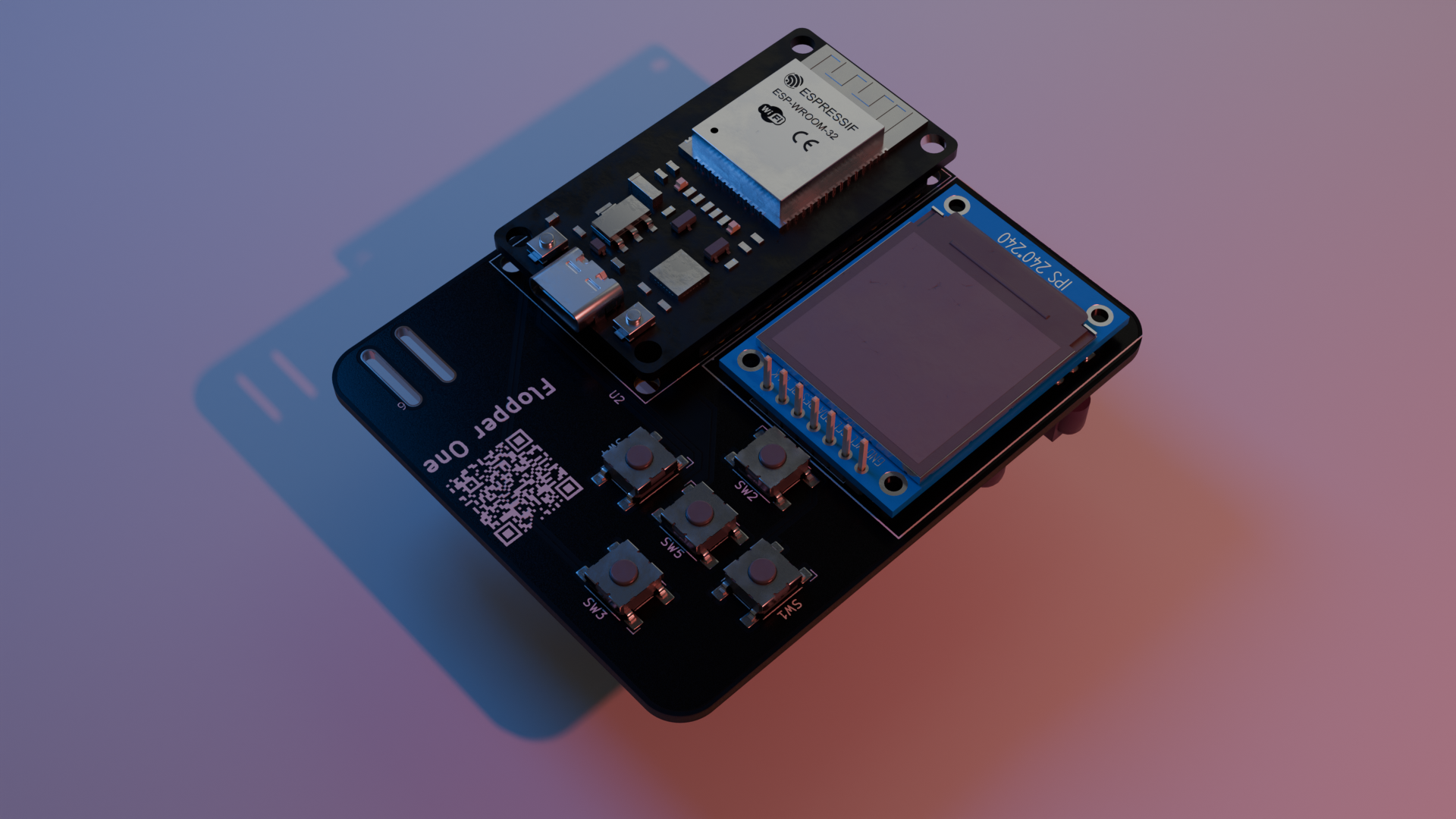
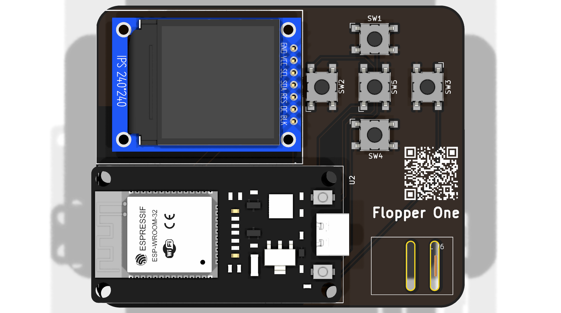
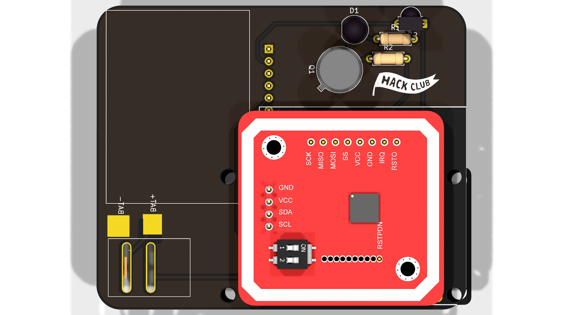
Flopper one is an open-source printed circuit board by JBlitzar, from the JBlitzar/flopper-one repository on GitHub, published under the GPL-3.0 licence. It is a 2-layer board of 76.8 × 63 mm with 14 parts on 33 nets, routed with 97 tracks and 0 vias.
It is built around the TSAL6200 and TSOP38238. Its parts include 6 switches, 2 resistors, 2 connectors, 1 IC and 1 diode. It belongs with the radio and wireless boards of this library.


|
|
Flipper zero-type firmware with an ESP32. Featuring IR, NFC, BLE, wifi, with a dpad and an lcd display. Not designed using any guide!
I've always thought that the flipper zero was pretty cool, but the $200 price point made it seem out of reach.
I joined up blueprint, made the hackpad, learned a lot and had a lot of fun.
Then I saw the sorta flipper zero. This was truly inspring. I saw it, and I thought to myself, I could totally do that. And it turns out I have like half the parts! The ESP has wifi and bluetooth built in (you usually need to pay like $60 extra for wifi on a flipper), all that's left is to add... all the other stuff.
Since this is my second PCB project, I opted for a module build. In the end, this made the pcb quite crowded and taught me a lot about good routing (and I still had to use the smd TP4056 IC, you'll see later)
Basically, after the ESP, we need a UI, IR, NFC, and RFID.
The UI is some buttons in a dpad and a display.
IR is incredibly easy. It's literally an LED (with some passives sprinkled in), and then a TSOP38238 to recieve.
For NFC/RFID, I opted for the PN532 module. I breifly entertained the idea of using the bare PN532 chip and fully integrating it, but the datasheet is 222 pages long and the application circuit (page 212, figure 51) seems pretty involved if I do say so myself.
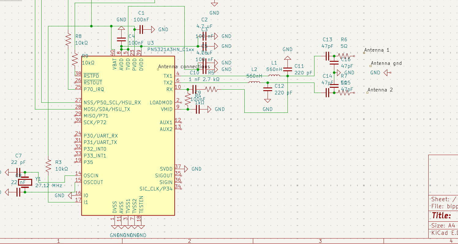
incomplete nfc circuit... yeah its pretty complicated
At this point it's cheaper AND smaller to just use the module. So that's what I did
Then I thought it'd be fun to add power management. "fun." If only it was simple like the xiao! I added the TP4056 IC because I was feeling fancy. I asked on slack, and it turns out you need a boost converter. To get your 3.7v battery up to 5v... so that it can go back down to 3.3v. I used a module for the boost converter. But I still got to add fun charging status LEDs! Also I got the "opportunity" to google translate Chinese datasheets.
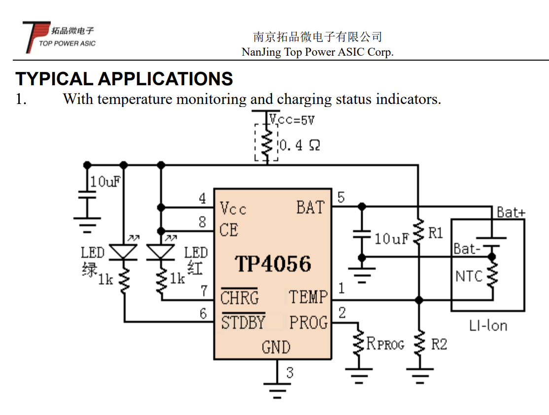
I also discovered some... interesting hacks like how the VIN pin on the esp is actually 5v out when the usb is plugged in. Meaning we can charge from VIN... and then later discharge also to VIN.
I added a physical switch to prevent backflow. So congratulations, users are now trusted with power supply logic!
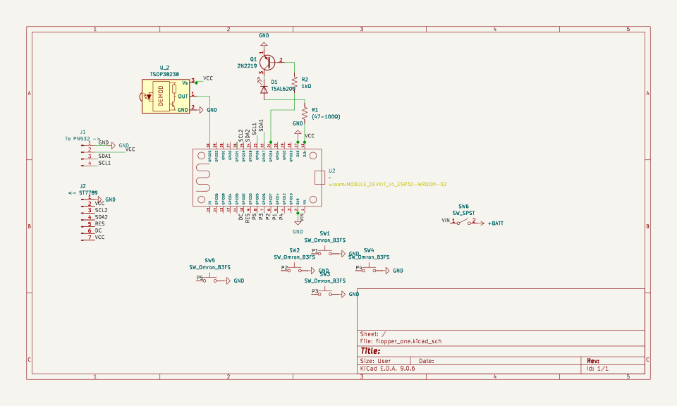
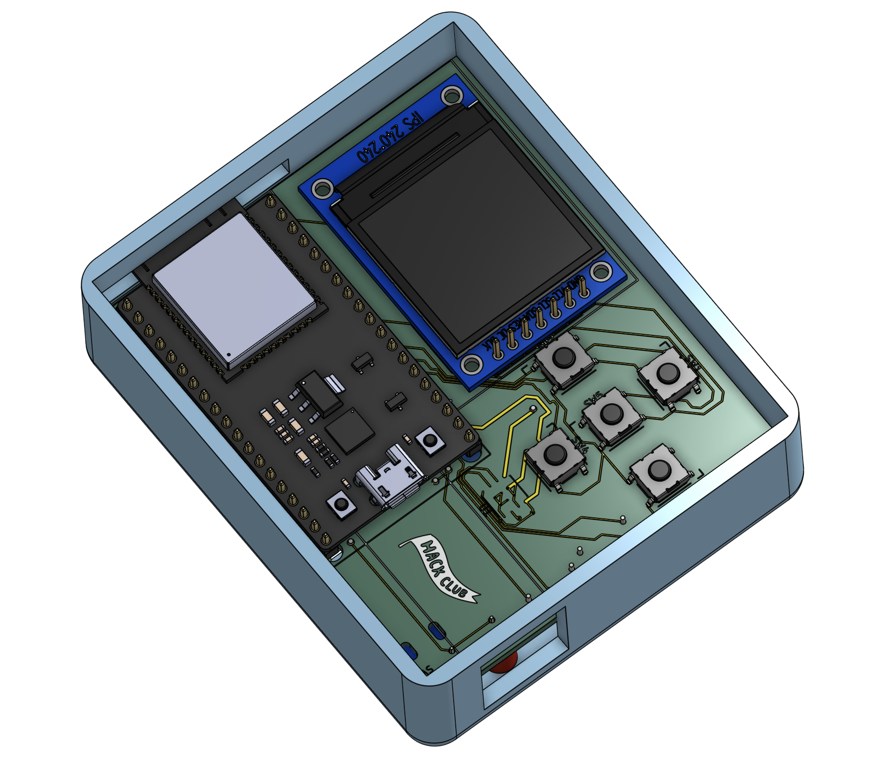
IMPORTANT: See CAD/README.md for notes.
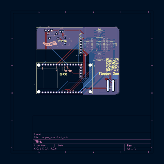
see BOM.csv.
This BOM format has been approved by the blueprint team
| Item | Link | Cost | Amount | total cost of | total | Gotten? |
|---|---|---|---|---|---|---|
| 32.15 | FALSE | |||||
| esp32 wroom | already own | 0 | 1 | 0 | TRUE | |
| TSOP38238 | https://www.lcsc.com/product-detail/C141632.html | 0.73 | 1 | 0.73 | FALSE | |
| TSAL6200 | https://www.lcsc.com/product-detail/C55528.html | 0.83 | 1 | 0.83 | FALSE | |
| PN532 | https://www.aliexpress.us/item/3256806254348567.html | 0.99 | 1 | 0.99 | FALSE | |
| ST7789 | https://www.aliexpress.us/item/2255799995721426.html | 3.57 | 1 | 3.57 | FALSE | |
| 5x b3fs | https://www.lcsc.com/product-detail/C271750.html | 1.07 | 1 | 1.07 | FALSE | |
| 5x TP4056 (moq) | https://www.lcsc.com/product-detail/C16581.html | 0.91 | 1 | 0.91 | FALSE | |
| lipo battery | already own | 0 | 1 | 0 | TRUE | |
| MT3608 module | https://www.aliexpress.us/item/3256808032184992.html? | 6.77 | 1 | 6.77 | FALSE | |
| 5x PCB (moq) | n/a | 5.3 | 1 | 5.3 | FALSE | |
| switch | already own | 0 | 1 | 0 | TRUE | |
| 1kΩ resistor | Can get for free | 0 | 3 | 0 | TRUE | |
| 47-100Ω resistor | Can get for free | 0 | 1 | 0 | TRUE | |
| 1.2kΩ resistor | Can get substitute for free | 0 | 1 | 0 | TRUE | |
| 10uf capacitor | can get for free | 0 | 2 | 0 | TRUE | |
| 2n2222a (2n2219 substitute) | https://www.lcsc.com/product-detail/C118536.html | 0.77 | 1 | 0.77 | FALSE | |
| LEDS (green, red) | already own | 0 | 2 | 0 | TRUE | |
| header pins | can get for free | 0 | 2 | 0 | TRUE | |
| aliexpress shipping | n/a | 0 | 1 | 0 | FALSE | |
| lcsc shipping | n/a | 11.21 | 1 | 11.21 | FALSE |
Plug the esp into your computer and flash the firmware in /firmware using platformIO in vscode. For now, firmware will run a self-test. In the future, once I verify hardware is working etc, I'll put more details about that in there. (once I have a real UI working)
The reason why firmware's a stub rn is explained in the firmware readme.
See more in firmware/README.md !
| Qty | Value | Footprint | References |
|---|---|---|---|
| 5 | SW_Omron_B3FS | Button_Switch_SMD:SW_SPST_Omron_B3FS-100xP | SW1, SW2, SW3, SW4, SW5 |
| 1 | (47-100Ω) | Resistor_THT:R_Axial_DIN0207_L6.3mm_D2.5mm_P7.62mm_Horizontal | R1 |
| 1 | 1kΩ | Resistor_THT:R_Axial_DIN0207_L6.3mm_D2.5mm_P7.62mm_Horizontal | R2 |
| 1 | 2N2219 | Package_TO_SOT_THT:TO-39-3 | Q1 |
| 1 | <- ST7789 | Connector_PinHeader_2.54mm:PinHeader_1x07_P2.54mm_Vertical | J2 |
| 1 | SW_SPST | wroom:my_switch | SW6 |
| 1 | TSAL6200 | LED_THT:LED_D5.0mm_IRBlack | D1 |
| 1 | TSOP38238 | OptoDevice:Vishay_MINICAST-3Pin | U_2 |
| 1 | To PN532 -> | Connector_PinHeader_2.54mm:PinHeader_1x04_P2.54mm_Vertical | J1 |
| 1 | ~ | wroom:MODULE_DEVKIT_V1_ESP32-WROOM-32 | U2 |
It measures 76.8 × 63 mm and has 2 copper layers, 1.6 mm thick.
14 parts, built around the TSAL6200 and TSOP38238. The full list of its parts is on this page, with links to each part's symbol and footprint where PCBKit's library has them.
From the JBlitzar/flopper-one repository on GitHub, at the commit this page was made from: the board is PCB/flopper_one/flopper_one.kicad_pcb and its schematic PCB/flopper_one/flopper_one.kicad_sch. PCBKit opens the board in the browser, with nothing to install.
Its repository publishes it under the GPL-3.0 licence: you may reuse it on that licence's terms (keep the author's notice, and for a copyleft licence share your changes alike).
ajvizganapathy-pixel/FlipperZero-DIY-STM32WB55-NucleusDark
DIY Flipper Zero clone using STM32WB55CGU6 — KiCad PCB, Momentum firmware, 200+ apps, BadUSB scripts, wiring diagrams

dmarcr1997/COR-SAT
COR-SAT turns natural-language mission requests into tested Python mission packages for a Raspberry Pi satellite payload.

AskAlice/home-automation-pcbs
Daily Kimi-generated home automation PCB designs with KiCad sources, 3D models, and rendered documentation

bikeNomad/micropython-tv-b-gone
A MicroPython version of the classic TV-B-Gone tool with new code database

maehw/DiyIrTower
Do-it-yourself infrared serial communication tower (compatible with LEGO IR serial tower)


cedric-dufour/LIRC-HighPowerSerialTransceiver
LIRC High-Power Serial Transceiver [CC-BY]

Samuel-Malaj/PicoCalc-Open-Source-Student-Scientific-Calculator
Open source scientific calculator built on Raspberry Pi Pico W — custom PCB, WiFi messaging, IR projector control and games.