
2 layers200 × 78.8 mm
Openridingcontroller rev2
Squalius-cephalus/OpenRidingController
D.I.Y horse riding controller for the PC.
30 parts13

 jaylamb/optical_tachometer_hardware
An optical tachometer printed circuit board based around the Vishay TCRT5000 reflective optical sensor.
Optical tachometer hardware is an open-source printed circuit board by jaylamb, from the jaylamb/optical_tachometer_hardware repository on GitHub, published under the Apache-2.0 licence. It is a 2-layer board of 21 × 24 mm with 11 parts on 7 nets, routed with 23 tracks and 3 vias.
It is built around the TCRT5000. Its parts include 4 resistors, 3 diodes, 1 capacitor, 1 transistor and 1 connector. It belongs with the sensors and measurement boards of this library.
The optical_tachometer_hardware project consists of a single printed circuit board (PCB)
which contains a TCRT5000 reflective sensor and its supporting circuitry. The device's
physical interface is a three position right-angle pin header.
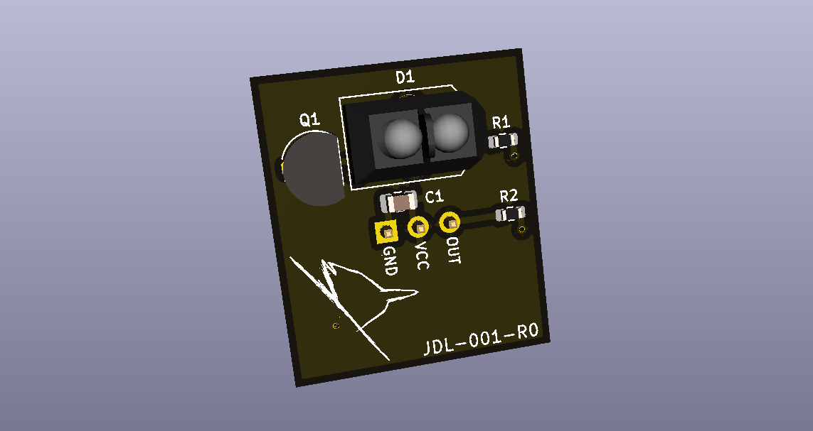
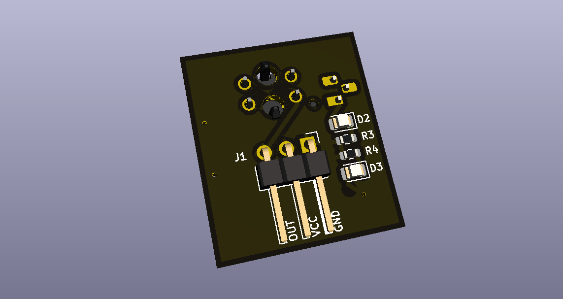
Built-up hardware is a sensor module designed to be interfaced with a General Purpose Input/Output (GPIO) pin on a microcontroller. The sensor is active-high, and asserts its output when in close proximity to a reflective object.
| Qty | Value | Footprint | References |
|---|---|---|---|
| 2 | 330 | Resistor_SMD:R_0603_1608Metric | R3, R4 |
| 1 | 0.1uF | Capacitor_SMD:C_0805_2012Metric | C1 |
| 1 | 100 | Resistor_SMD:R_0603_1608Metric | R1 |
| 1 | 10k | Resistor_SMD:R_0603_1608Metric | R2 |
| 1 | 2N2222 | Package_TO_SOT_THT:TO-92_HandSolder | Q1 |
| 1 | BLUE | LED_SMD:LED_0805_2012Metric | D3 |
| 1 | GREEN | LED_SMD:LED_0805_2012Metric | D2 |
| 1 | J1 | Connector_PinHeader_2.54mm:PinHeader_1x03_P2.54mm_Horizontal | J1 |
| 1 | LOGO | graphics:jaybird-logo-small | G*** |
| 1 | TCRT5000 | vishay:tcrt5000 | D1 |
It measures 21 × 24 mm and has 2 copper layers, 1.6 mm thick.
11 parts, built around the TCRT5000. The full list of its parts is on this page, with links to each part's symbol and footprint where PCBKit's library has them.
From the jaylamb/optical_tachometer_hardware repository on GitHub, at the commit this page was made from: the board is optical_tachometer_hardware.kicad_pcb. PCBKit opens the board in the browser, with nothing to install.
Its repository publishes it under the Apache-2.0 licence: you may reuse it on that licence's terms (keep the author's notice, and for a copyleft licence share your changes alike).
Squalius-cephalus/OpenRidingController
D.I.Y horse riding controller for the PC.


xtarke/automated_buggy
This shield connects microcontroller (MSP-EXP430FR2355) pins to the car's power board. Go to Power Board for more hardware information.

Amrlxyz/esp-lfr-buggy
2nd Year Embedded Systems Project (ESP) - Line Following Robot Buggy


ciiiutnfrc/eduromaa
Versión educativa del robot móvil RoMAA (EduRoMAA)

billtsol/Maze
This project demonstrates how to use an Arduino board, IR sensors, and a motor driver shield to create a maze-solving robot.

Potato-eater/Legacy2026
github repo for Robocup Junior Australia lightweight soccer team