4 layers102 × 49 mm
CURSO PCB DRONE
ArduProject/PCB_DRONE_C8
En este repositorio encontrareis los archivos de fabricación y las listas de montaje del PCB con STM32F103C8 que hemos visto en el curso.
153 parts1MIT
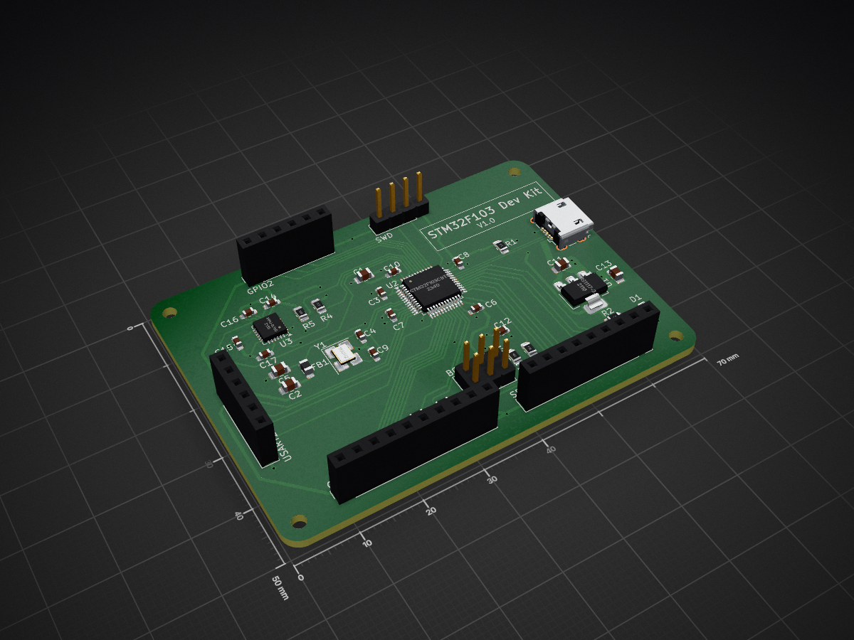
 jayasinghedr/stm32f103-devkit
A development board with STM32F103C8T6 and an MPU6050 IMU
Stm32f103-imu test kit is an open-source printed circuit board by jayasinghedr, from the jayasinghedr/stm32f103-devkit repository on GitHub, published under the MIT licence. It is a 2-layer board of 70 × 50 mm with 42 parts on 66 nets, routed with 438 tracks and 40 vias.
It is built around the STM32F103C8T6, AMS1117-3.3 and MPU-6050. Its parts include 17 capacitors, 8 resistors, 7 connectors, 3 ICs and 1 diode. It belongs with the sensors and measurement boards and the STM32 boards of this library.


| Qty | Value | Footprint | References |
|---|---|---|---|
| 9 | 100n | Capacitor_SMD:C_0603_1608Metric_Pad1.08x0.95mm_HandSolder | C3, C6, C8, C10, C12, C14, C15, C16, C17 |
| 4 | 4k7 | Resistor_SMD:R_0805_2012Metric_Pad1.20x1.40mm_HandSolder | R4, R5, R7, R8 |
| 4 | MountingHole | MountingHole:MountingHole_2.2mm_M2 | H1, H2, H3, H4 |
| 2 | 10p | Capacitor_SMD:C_0603_1608Metric_Pad1.08x0.95mm_HandSolder | C4, C9 |
| 2 | 1u | Capacitor_SMD:C_0805_2012Metric_Pad1.18x1.45mm_HandSolder | C2, C5 |
| 2 | 22u | Capacitor_SMD:C_0805_2012Metric_Pad1.18x1.45mm_HandSolder | C11, C13 |
| 1 | 100K | Resistor_SMD:R_0805_2012Metric_Pad1.20x1.40mm_HandSolder | R3 |
| 1 | 100k | Resistor_SMD:R_0805_2012Metric_Pad1.20x1.40mm_HandSolder | R6 |
| 1 | 10n | Capacitor_SMD:C_0603_1608Metric_Pad1.08x0.95mm_HandSolder | C7 |
| 1 | 10u | Capacitor_SMD:C_0805_2012Metric_Pad1.18x1.45mm_HandSolder | C1 |
| 1 | 120R | Inductor_SMD:L_0805_2012Metric_Pad1.05x1.20mm_HandSolder | FB1 |
| 1 | 16MHz | Crystal:Crystal_SMD_3225-4Pin_3.2x2.5mm_HandSoldering | Y1 |
| 1 | 1k | Resistor_SMD:R_0805_2012Metric_Pad1.20x1.40mm_HandSolder | R2 |
| 1 | 1k5 | Resistor_SMD:R_0805_2012Metric_Pad1.20x1.40mm_HandSolder | R1 |
| 1 | AMS1117-3.3 | Package_TO_SOT_SMD:SOT-223-3_TabPin2 | U1 |
| 1 | BOOT_CONFIG | Connector_PinHeader_2.54mm:PinHeader_2x03_P2.54mm_Vertical | J4 |
| 1 | GPIO1 | Connector_PinSocket_2.54mm:PinSocket_1x09_P2.54mm_Vertical | J5 |
| 1 | GPIO2 | Connector_PinSocket_2.54mm:PinSocket_1x06_P2.54mm_Vertical | J3 |
| 1 | LED | LED_SMD:LED_0805_2012Metric_Pad1.15x1.40mm_HandSolder | D1 |
| 1 | MPU-6050 | Sensor_Motion:InvenSense_QFN-24_4x4mm_P0.5mm | U3 |
| 1 | SPI1_ADC1_I2C2 | Connector_PinSocket_2.54mm:PinSocket_1x10_P2.54mm_Vertical | J7 |
| 1 | STM32F103C8T6 | Package_QFP:LQFP-48_7x7mm_P0.5mm | U2 |
| 1 | SWD | Connector_PinHeader_2.54mm:PinHeader_1x04_P2.54mm_Vertical | J6 |
| 1 | USART2 | Connector_PinSocket_2.54mm:PinSocket_1x06_P2.54mm_Vertical | J2 |
| 1 | USB_B_Micro | Connector_USB:USB_Micro-B_Wuerth_629105150521 | J1 |
It measures 70 × 50 mm and has 2 copper layers, 1.6 mm thick.
42 parts, built around the STM32F103C8T6, AMS1117-3.3 and MPU-6050. The full list of its parts is on this page, with links to each part's symbol and footprint where PCBKit's library has them.
From the jayasinghedr/stm32f103-devkit repository on GitHub, at the commit this page was made from: the board is kicad/stm32f103-imu-test-kit.kicad_pcb and its schematic kicad/stm32f103-imu-test-kit.kicad_sch. PCBKit opens the board in the browser, with nothing to install.
Its repository publishes it under the MIT licence: you may reuse it on that licence's terms (keep the author's notice, and for a copyleft licence share your changes alike).
ArduProject/PCB_DRONE_C8
En este repositorio encontrareis los archivos de fabricación y las listas de montaje del PCB con STM32F103C8 que hemos visto en el curso.

dark-Phoenix2077/hover
A fully custom mini racing/stunt drone with ML-assisted balancing, automatic stunts, and some level of autonomous operation without costly cameras or GPS.

Ferid10/STM32F103C8T6-design
my pcb design where i made a stm 32 board with temprature and pressure sensor using both spi and i2c communication


zenitheesc/Zenith-Development-Board
The Zenith Development Board was developed to serve as a first project for the new members of the group.


hardenedlinux/cheap-pcb
Cheap PCB: Better understanding the current status of hardware supply chain