4 layers116 × 106 mm
Card
increpare/PuzzleScript-labs
firehose of mostly ai-written puzzlescript projects. main project is https://github.com/increpare/puzzlescript/
48 parts1MIT

 jay-lchicken/BlinkIR
I will reorganise the files into the folders. However, for the cost optimisation, it is not really possible for this project since the LEDs cannot be on the same side as the phototransistor and thus require a…
BlinkIR is an open-source printed circuit board by jay-lchicken, from the jay-lchicken/BlinkIR repository on GitHub. It is a 2-layer board of 25.5 × 65.6 mm with 68 parts on 49 nets, routed with 563 tracks and 37 vias.
It is built around the TPS63070RNMT, NTD3528I7 and MPT60363T, with the SK6812 and KMR221GLFS among its other parts. Its parts include 22 resistors, 10 capacitors, 10 diodes, 9 ICs and 3 connectors.


"Hey! Cool project, but it needs to be polished a bit before it can be approved, you can organise the files in speicific folders such as PCB/etc. I also believe this can be cost optimized a lot, please take a look at the docs, right now you can get 54$ worth of grant for the project but your BOM is totalling to 3 times of that, you should save costs on the PCBA, by trying to fit all components on one side, using components only from standard libray, getting only 2 pcba rather than 5, etc."
I will reorganise the files into the folders. However, for the cost optimisation, it is not really possible for this project since the LEDs cannot be on the same side as the phototransistor and thus require a double-sided assembly. Getting only 2pcba rather than 5 only saves $10, so I may as well go with 5. I can pay the extra price that the grant cannot cover. also, some components are really big and cannot be on the same side as phototransistor else it would hit the ground, like the 47uf electrolytic capacitor
"Hey! I understand you don't have a case but we want to see polished projects so a basic enclosure/case is required! Please add it" This project is supposed to be an open source sensor that everyone can attatch to their robots or machines. hence, there is no casing for it
I created this project when I saw a super fast line tracing robot. I thought about what was needed and since one of the most crucial components for a line tracing robot is the IR Array Sensor, I decided
What if I can make one of the most responsive and feature-packed IR Sensor ever made.
I took inspiration from the Pololu QTR-8A. It is equipped with 8 IR emitters and 8 IR Recievers (or maybe phototransistors, I'm not sure).
I did the same and put it into my PCB with 8 IR emitters and 8 phototransistors that uses the voltage divider rule to give users the reading.
Doing this, I realised that the project ended up being just a normal IR Array sensor. I thought hard about how I could make it unique. Personally, I have building robots since young and it came to my mind that if I can solve all the problems I previously had with a robot by implementing the solution in the PCB, it would be great!
I usually hate using the Serial Monitor when debugging my hardware code, so I decided to add 8 SK6812 Neopixel indicator lights to the pcb, one for each IR Sensor but on the other side of the PCB. The user can have full control of the LEDs but for me, I want to be able to change the light depending on what the phototransistor detects. This helps make debugging with the IR array sensor a lot easier. When testing line tracking, I can also easily see how I can fine tune the robot when line tracking by looking at the LEDs which I can program to light up when it detects a certain black that meets the treshold value
Competitive robots require a Start/Stop button which I normally use jumper wires to implement. However, these wires often get loose and prevent the robot from starting. Since I am already desiging a PCB, I might as well put some buttons
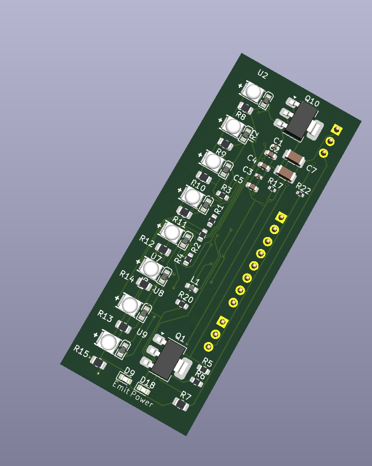
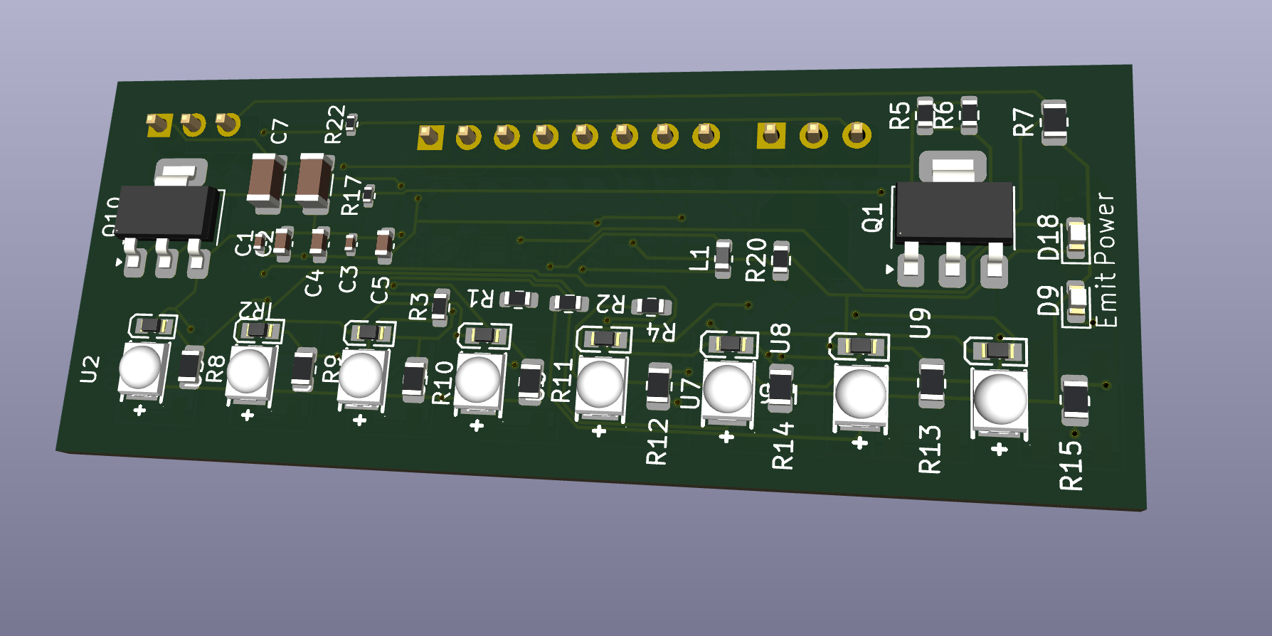
I added a Buck-Boost converter which allow you to put 3.3V to 12V into the IR array sensor. Then, the converter will convert it to 5V which is the proper operating voltage for the circuit. There are 8 pins which the users can tap into individually with their microcontroller to read the phototransistor readings. There are also another 3 pins. Two for the two INPUT_PULLUP Buttons as well as one for contorlling the daisy chained SK6812 Neopixel LEDs. Lastly, there are another 3 pins for Vin, GND and turning on the IR Emitter
I decided to go with 4.7K resistors for the phototransistors, this helps balance between the noise and speed for the IR Array Sensor


| Part Number | Selected By | Qty | Cost |
|---|---|---|---|
| FRC1206F4700TS | System | 15 | $0.08 |
| 0402WGF3300TCE | System | 20 | $0.02 |
| CL10A106KP8NNNC | System | 40 | $0.36 |
| 0603WAF1003T5E | System | 40 | $0.03 |
| NTD3528I7 | System | 44 | $1.66 |
| TPS63070RNMT | System | 5 | $8.42 |
| CL31A226KAHNNNE | System | 14 | $2.50 |
| 0805W8F4702T5E | System | 20 | $0.04 |
| 0805W8F5233T5E | System | 20 | $0.05 |
| KT-0603W | System | 20 | $0.24 |
| RVT102470M0505 | Customer | 20 | $0.58 |
| SK6812 | System | 42 | $3.73 |
| 0805W8F4701T5E | System | 46 | $0.10 |
| 2.54-1×3P# | Customer | 12 | $0.29 |
| MPT0603GT | System | 44 | $1.83 |
| CL05B104K05NNNC | System | 40 | $0.05 |
| 1206W4F1002T5E | System | 15 | $0.09 |
| CMI060808U22RK7 | System | 20 | $0.34 |
| JSM2302 | Customer | 15 | $0.30 |
| CL10A105KB8NNNC | System | 20 | $0.22 |
| KMR221GLFS | System | 10 | $5.31 |
| 0603WAF470J5E | System | 40 | $0.08 |
| Category | Amount |
|---|---|
| Merchandise Total (incl. assembly) | $153.07 |
| Shipping (Estimated) | $8.85 |
| Subtotal | $161.92 |
| Qty | Value | Footprint | References |
|---|---|---|---|
| 8 | 4.7k | Resistor_SMD:R_0805_2012Metric | R8, R9, R10, R11, R12, R13, R14, R15 |
| 8 | MPT60363T | easyeda2kicad:OPTO-SMD_L1.7-W0.8 | IR1, IR2, IR3, IR4, IR5, IR6, IR7, IR8 |
| 8 | NTD3528I7 | easyeda2kicad:LED-SMD_L3.5-W2.8-FD-1 | U2, U3, U4, U5, U6, U7, U8, U9 |
| 8 | SK6812 | LED_SMD:LED_SK6812_PLCC4_5.0x5.0mm_P3.2mm | D10, D11, D12, D13, D14, D15, D16, D17 |
| 6 | 47 | Resistor_SMD:R_0603_1608Metric | R1, R2, R3, R4, R5, R6 |
| 2 | 0.1uF | Capacitor_SMD:C_0402_1005Metric | C1, C3 |
| 2 | 1.0uF | Capacitor_SMD:C_0603_1608Metric | C2, C4 |
| 2 | 100k | Resistor_SMD:R_0603_1608Metric | R18, R20 |
| 2 | 10uF | Capacitor_SMD:C_0603_1608Metric | C5, C9 |
| 2 | 22uF | Capacitor_SMD:C_1206_3216Metric | C6, C7 |
| 2 | 330 | Resistor_SMD:R_0402_1005Metric | R17, R22 |
| 2 | Conn_01x03_Pin | Connector_PinHeader_2.54mm:PinHeader_1x03_P2.54mm_Vertical | J1, J4 |
| 2 | KMR221GLFS | easyeda2kicad:KEY-SMD_KMR2XXGXXX | SW1, SW3 |
| 2 | LED | LED_SMD:LED_0603_1608Metric | D9, D18 |
| 2 | NMOS | Package_TO_SOT_SMD:SOT-223 | Q1, Q10 |
| 1 | 100nF | Capacitor_SMD:C_0402_1005Metric | C8 |
| 1 | 10k | Resistor_SMD:R_1206_3216Metric | R16 |
| 1 | 2.2uH | Inductor_SMD:L_0603_1608Metric | L1 |
| 1 | 470 | Resistor_SMD:R_1206_3216Metric | R21 |
| 1 | 47k | Resistor_SMD:R_0805_2012Metric | R7 |
| 1 | 47uF | Capacitor_SMD:CP_Elec_5x5.4 | C10 |
| 1 | 523k | Resistor_SMD:R_0805_2012Metric | R19 |
| 1 | Conn_01x08_Pin | Connector_PinHeader_2.54mm:PinHeader_1x08_P2.54mm_Vertical | J2 |
| 1 | SolderJumper_2_Open | Jumper:SolderJumper-2_P1.3mm_Open_Pad1.0x1.5mm | JP1 |
| 1 | TPS63070RNMT | TPS63070RNMT:VREG_TPS63070RNMT | U1 |
It measures 25.5 × 65.6 mm and has 2 copper layers, 1.6 mm thick.
68 parts, built around the TPS63070RNMT, NTD3528I7, MPT60363T and SK6812. The full list of its parts is on this page, with links to each part's symbol and footprint where PCBKit's library has them.
From the jay-lchicken/BlinkIR repository on GitHub, at the commit this page was made from: the board is pcb/BlinkIR.kicad_pcb and its schematic pcb/BlinkIR.kicad_sch. PCBKit opens the board in the browser, with nothing to install.
Its repository states no licence, so its author keeps all rights: ask jay-lchicken before reusing the design.
increpare/PuzzleScript-labs
firehose of mostly ai-written puzzlescript projects. main project is https://github.com/increpare/puzzlescript/

SuperPower/Apollo
All hardware designs and products you can find in this repository is licensed under CERN Open Hardware Licence Version 2 - Weakly Reciprocal

loxodes/vna
Under development open hardware microwave vector network analyzer

themainframe/5g-m2-usb3-interface-pcb
KiCad EDA Project for my 5G M.2 (NGFF) USB3 Interface board

ErichStyger/McuLink-Mini
Version of the NXP MCU-Link Debug CMSIS-DAP Debug Probe.

ErichStyger/MCU-Link-MR
Open Source MCU-Link CMSIS-DAP Debug probe for mobile robots (e.g. Pixhawk)

themainframe/p3-cellular-module
CAD/CAM for a GPD Pocket 3 Cellular Module
