4 layers42 × 55.8 mm
P3-cellular module
themainframe/p3-cellular-module
CAD/CAM for a GPD Pocket 3 Cellular Module
54 parts14

 themainframe/5g-m2-usb3-interface-pcb80
KiCad EDA Project for my 5G M.2 (NGFF) USB3 Interface board
Usb3-ngff carrier is an open-source printed circuit board by themainframe, from the themainframe/5g-m2-usb3-interface-pcb repository on GitHub, published under the MIT licence. It is a 4-layer board of 90 × 40 mm with 62 parts on 75 nets, routed with 1,303 tracks and 403 vias.
It is built around the MBRA340, SIM8060-6-1-14-00-A and KMR221GLFS, with the KUSBX-BS1N9-1-BL30 among its other parts. Its parts include 23 capacitors, 14 resistors, 6 connectors, 4 diodes and 1 IC. It belongs with the computers and single-board computers boards of this library.


I’ve been experimenting with 5G cellular modules recently, and found that many of the M.2 break-out boards that run on just USB power (mostly designed for 4G modules) can’t supply the required current at the peaks during transmission. I decided to design my own in KiCad with dual-power input, Nano-SIM slot, and USB 3 to support the required data rates for 5G.
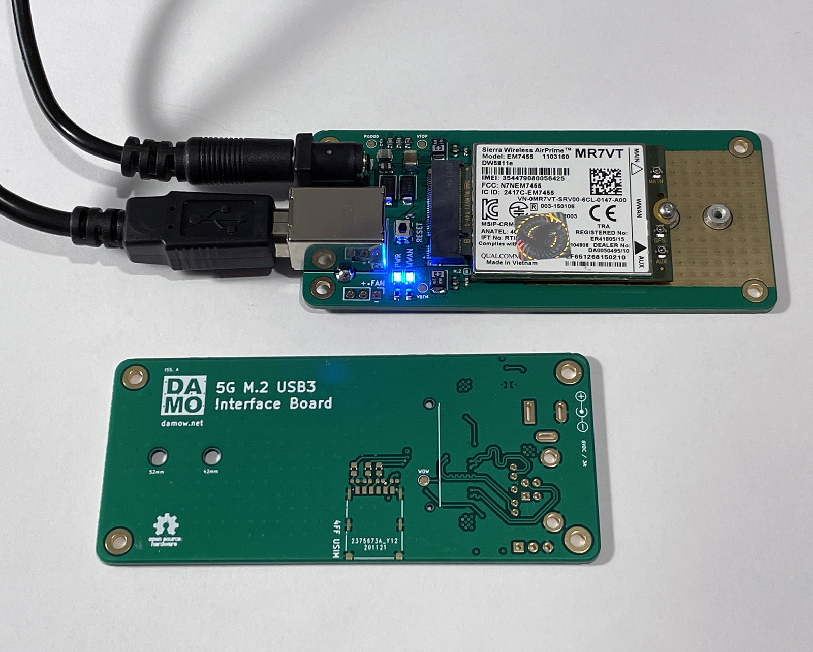
I'm using mine with a Quectel RM500Q-GL 5G module that I've previously blogged about. The design very much obeys the appnote recommendations for the RM500Q-GL module so use with that one especially should work fine.
4 layers. Standard FR4. ENIG recommended for easier soldering of the fine-pitch parts (M.2 connector & TPS82130SILR DC-DC converter)
BOM can be found in the bom/ directory. Currency is GBP. Total build cost (excluding non-special caps & resistors) is ~£15 in 10qty.
Open an issue or drop me an email - me@ my blog domain.
| Qty | Value | Footprint | References |
|---|---|---|---|
| 9 | 33pF | Capacitor_SMD:C_0603_1608Metric | C7, C12, C14, C17, C18, C19, C21, C22, C23 |
| 6 | 22R | Resistor_SMD:R_0603_1608Metric | R6, R7, R8, R10, R11, R12 |
| 5 | 100nF | Capacitor_SMD:C_0603_1608Metric | C2, C6, C11, C16, C20 |
| 3 | 10k | Resistor_SMD:R_0603_1608Metric | R3, R13, R14 |
| 3 | 330R | Resistor_SMD:R_0603_1608Metric | R1, R4, R9 |
| 2 | 100uF | Capacitor_Tantalum_SMD:CP_EIA-3528-21_Kemet-B | C4, C9 |
| 2 | 10pF | Capacitor_SMD:C_0603_1608Metric | C8, C13 |
| 2 | 1uF | Capacitor_SMD:C_0603_1608Metric | C5, C10 |
| 2 | 22uF | Capacitor_SMD:C_1210_3225Metric | C3, C15 |
| 2 | LED | LED_SMD:LED_0805_2012Metric | D3, D4 |
| 2 | M2 Threaded Insert | footprint:9774015243RStandoff | H1, H2 |
| 2 | MBRA340 | Diode_SMD:D_SMA | D1, D2 |
| 2 | SIM8060-6-1-14-00-A | footprint:GCT_SIM8060-6-1-14-00-A | J4, J6 |
| 1 | 0R | Resistor_SMD:R_0603_1608Metric | R2 |
| 1 | 10uF | Capacitor_SMD:C_0805_2012Metric | C1 |
| 1 | 2.2uH | Inductor_SMD:L_Coilcraft_XAL5030 | L1 |
| 1 | 2199119-3 | footprint:TE_2199119-3 | J2 |
| 1 | 36k5 | Resistor_SMD:R_0603_1608Metric | R5 |
| 1 | AP62301WU7 | Package_TO_SOT_SMD:TSOT-23-6 | U1 |
| 1 | Conn_01x03_Male | Connector_PinHeader_2.54mm:PinHeader_1x03_P2.54mm_Vertical | J5 |
| 1 | Jack-DC | Connector_BarrelJack:BarrelJack_Wuerth_6941xx301002 | J3 |
| 1 | KMR221GLFS | footprint:CK-KMR221GLFS-MFG | SW1 |
| 1 | KUSBX-BS1N9-1-BL30 | footprint:Wurth-692221030100-0-0-MFG | J1 |
| 1 | LOGO | LogosAndSilkscreens:damo-8mm | G*** |
| 1 | VBTM | TestPoint:TestPoint_Pad_D1.5mm | TP2 |
| 1 | VTOP | TestPoint:TestPoint_Pad_D1.5mm | TP1 |
| 1 | WOW | TestPoint:TestPoint_Pad_D1.5mm | TP4 |
The 56 most common of 62 parts.
It measures 90 × 40 mm and has 4 copper layers, 1.6 mm thick.
62 parts, built around the MBRA340, SIM8060-6-1-14-00-A, KMR221GLFS and KUSBX-BS1N9-1-BL30. The full list of its parts is on this page, with links to each part's symbol and footprint where PCBKit's library has them.
From the themainframe/5g-m2-usb3-interface-pcb repository on GitHub, at the commit this page was made from: the board is usb3-ngff-carrier.kicad_pcb. PCBKit opens the board in the browser, with nothing to install.
Its repository publishes it under the MIT licence: you may reuse it on that licence's terms (keep the author's notice, and for a copyleft licence share your changes alike).
themainframe/p3-cellular-module
CAD/CAM for a GPD Pocket 3 Cellular Module


kenyattaejones32-boop/AQM
Open-source hardware design for OpenHAP, an ESP32-based air quality monitor with CO sensing, thermistor temperature input, USB-C charging, and cellular data upload.


themainframe/led-matrix-driver-pcb
PCB CAM files for my LED Matrix Driver Project based on ESP32
