
2 layers40 × 40 mm
NeoBoard
alvaroferran/NeoBoard
Robotics controller shield for the NanoPi Neo Air with two DC motor drivers and a LiPo battery charger
73 parts3

100kHz to 6GHz 2 port USB based VNA
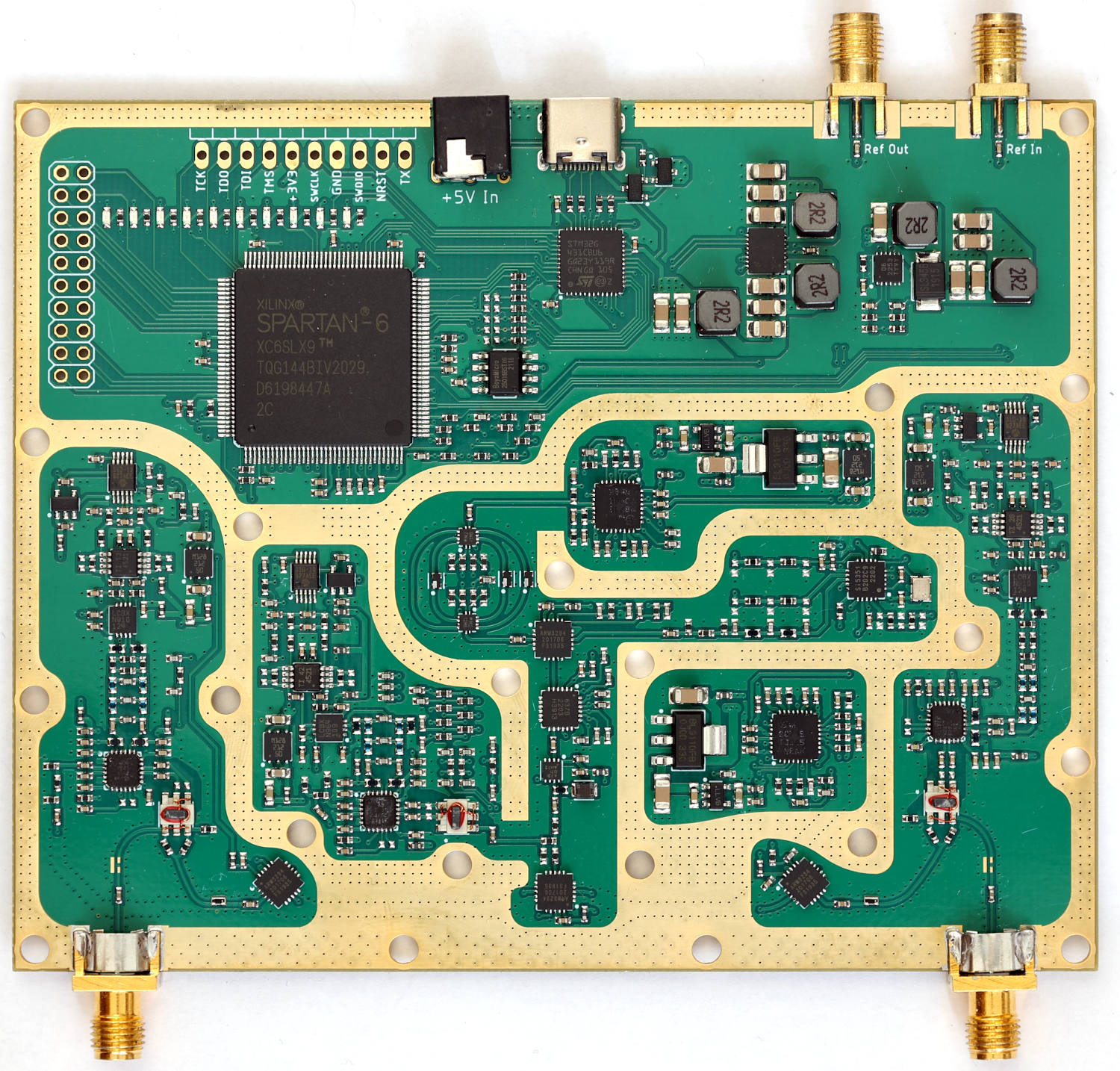
VNA is an open-source printed circuit board by jankae, from the jankae/LibreVNA repository on GitHub, published under the GPL-3.0 licence. It is a 6-layer board of 122 × 98 mm with 592 parts on 439 nets, routed with 3,586 tracks and 2,932 vias.
It is built around the STM32G431CBU6, QPC6324SR and LT5560EDD#PBF, with the MAX2871ETJ+, RFSW6042TR7 and RFSA3714TR13 among its other parts. Its parts include 274 capacitors, 165 resistors, 65 inductors, 37 ICs and 11 diodes. It belongs with the radio and wireless boards and the STM32 boards of this library.



100kHz to 6GHz VNA
This is the improved version of my first attempt at a VNA.
sudo apt install libusb-1.0-0 libqt6widgets6 libqt6svg6 libqt6network6wget https://raw.githubusercontent.com/jankae/LibreVNA/master/Software/PC_Application/51-vna.rules
sudo cp 51-vna.rules /etc/udev/rules.dsudo udevadm control --reload-rules
sudo udevadm triggercd $UNPACKED_ZIP_FOLDER$
./LibreVNA-GUIlatest in the name.13.7 in the name./Applications folder.Please also take a look at the FAQ.
If you notice bugs or have ideas for improvements, please create an issue for that.
For general questions or discussions, the LibreVNA group is probably the best place.
Some specifications are available but this project is still under development and the specifications might change.
There are also some initial example measurements.
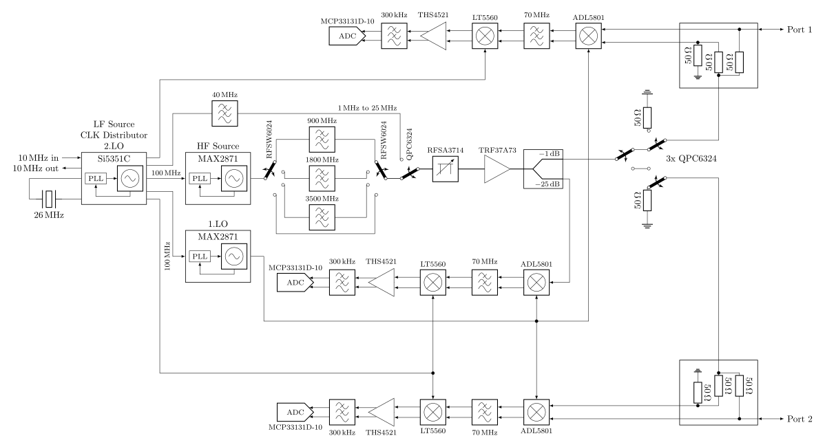
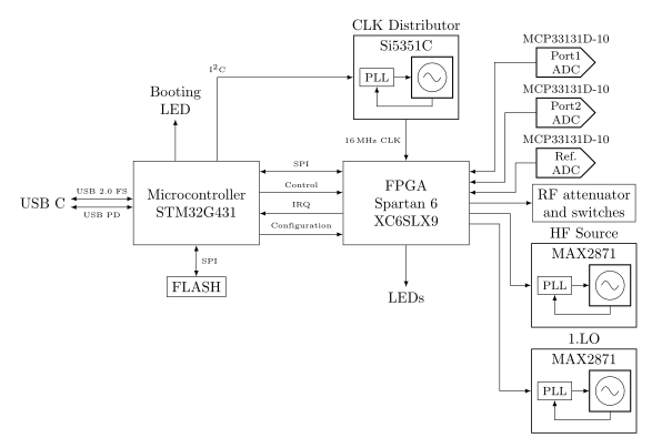
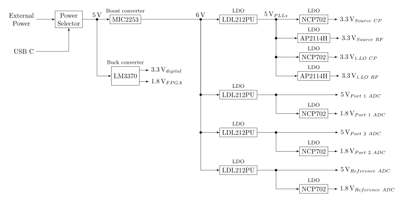
The PCB is really only the RF frontend with some processing power. Everything else is handled in the PC application once the data is transferred via USB. You can try out the application without the PCB (obviously no measurements are possible, but you can import provided example measurements and get an idea about what it can and can't do).
| Qty | Value | Footprint | References |
|---|---|---|---|
| 83 | 100nF | Capacitor_SMD:C_0402_1005Metric | C102, C103, C114, C115, C116, C117, C118, C119, C122, C132, C134, C135, C139, C140, C151, C152 +67 |
| 51 | 100pF | Capacitor_SMD:C_0402_1005Metric | C223, C224, C225, C226, C227, C228, C229, C230, C231, C232, C233, C234, C235, C236, C237, C238 +35 |
| 48 | 10k | Resistor_SMD:R_0402_1005Metric | R11, R116, R117, R121, R122, R125, R127, R128, R129, R130, R131, R132, R133, R143, R144, R145 +32 |
| 32 | FERRITE | Resistor_SMD:R_0402_1005Metric | L10, L12, L13, L15, L16, L17, L19, L20, L21, L22, L23, L25, L26, L27, L28, L29 +16 |
| 24 | 10nF | Capacitor_SMD:C_0402_1005Metric | C104, C105, C106, C111, C120, C123, C141, C142, C143, C148, C157, C160, C171, C172, C175, C180 +8 |
| 21 | 1uF | Capacitor_SMD:C_0402_1005Metric | C58, C100, C101, C108, C129, C131, C137, C138, C145, C166, C168, C177, C195, C198, C202, C203 +5 |
| 19 | TestPoint | VNA:B1,27 | TP1, TP2, TP3, TP4, TP5, TP6, TP10, TP11, TP12, TP13, TP14, TP15, TP16, TP17, TP18, TP19 +3 |
| 18 | 220R | Resistor_SMD:R_0402_1005Metric | R53, R54, R58, R59, R61, R62, R80, R81, R85, R86, R88, R89, R96, R97, R102, R103 +2 |
| 18 | DNP | Capacitor_SMD:C_0402_1005Metric | C35, C36, C37, C40, C41, C42, C44, C107, C112, C113, C144, C149, C150, C173, C174, C176 +2 |
| 17 | 10uF | Capacitor_SMD:C_1206_3216Metric | C1, C2, C3, C7, C8, C10, C11, C12, C13, C14, C15, C16, C17, C49, C53, C78 +1 |
| 15 | 100nF/RF | Capacitor_SMD:C_0402_1005Metric | C65, C68, C71, C74, C96, C99, C109, C110, C133, C136, C146, C147, C170, C178, C179 |
| 15 | 330nH | Inductor_SMD:L_0402_1005Metric | L14, L18, L24, L30, L31, L32, L33, L38, L39, L40, L41, L46, L47, L52, L53 |
| 14 | 49.9R | Resistor_SMD:R_0402_1005Metric | R12, R13, R14, R32, R33, R34, R35, R38, R45, R46, R50, R72, R73, R76 |
| 13 | 0R | Resistor_SMD:R_0402_1005Metric | R41, R42, R43, R44, R51, R52, R104, R105, R106, R107, R108, R109, R110 |
| 12 | 330R | Resistor_SMD:R_0402_1005Metric | R17, R39, R120, R134, R135, R136, R137, R138, R139, R140, R141, R142 |
| 12 | 330pF | Capacitor_SMD:C_0402_1005Metric | C121, C125, C126, C127, C158, C162, C163, C164, C184, C187, C188, C189 |
| 11 | 1uF | Capacitor_SMD:C_0603_1608Metric | C18, C19, C20, C21, C26, C27, C28, C50, C52, C79, C81 |
| 10 | 100R | Resistor_SMD:R_0402_1005Metric | R7, R9, R67, R68, R70, R74, R75, R78, R79, R164 |
| 9 | 20R | Resistor_SMD:R_0402_1005Metric | R64, R65, R91, R92, R118, R119, R123, R124, R126 |
| 8 | DNP | Resistor_SMD:R_0402_1005Metric | R57, R84, R100, R111, R112, R113, R114, R115 |
| 6 | 33nH | Inductor_SMD:L_0402_1005Metric | L36, L37, L44, L45, L50, L51 |
| 6 | 68nH | Inductor_SMD:L_0402_1005Metric | L34, L35, L42, L43, L48, L49 |
| 6 | Green | LED_SMD:LED_0603_1608Metric | LED2, LED6, LED7, LED8, LED9, LED10 |
| 5 | 2.2uH | Inductor_SMD:L_Sunlord_SWPA5040S | L1, L2, L3, L4, L5 |
| 5 | 56R | Resistor_SMD:R_0402_1005Metric | R28, R63, R66, R90, R93 |
| 4 | 4u7F | Capacitor_SMD:C_0603_1608Metric | C22, C23, C24, C25 |
| 4 | 6.8k | Resistor_SMD:R_0402_1005Metric | R55, R56, R82, R83 |
| 4 | LDL212PU50R | Package_SON:WSON-6-1EP_3x3mm_P0.95mm | IC3, IC4, IC5, IC6 |
| 4 | PAT0816-C-3DB-T5 | VNA:PAT0816 | R40, R47, R48, R49 |
| 4 | QPC6324 | Package_DFN_QFN:QFN-20-1EP_4x4mm_P0.5mm_EP2.5x2.5mm | IC13, IC16, IC17, IC18 |
| 4 | Red | LED_SMD:LED_0603_1608Metric | LED1, LED3, LED4, LED5 |
| 3 | 120pF | Capacitor_SMD:C_0402_1005Metric | C124, C161, C194 |
| 3 | 150pF | Capacitor_SMD:C_0402_1005Metric | C128, C165, C196 |
| 3 | 180pF | Capacitor_SMD:C_0402_1005Metric | C43, C63, C90 |
| 3 | 1k | Resistor_SMD:R_0402_1005Metric | R60, R87, R101 |
| 3 | 33pF | Capacitor_SMD:C_0402_1005Metric | C130, C167, C197 |
| 3 | 4.7k | Resistor_SMD:R_0402_1005Metric | R2, R94, R95 |
| 3 | ADL5801 | Package_DFN_QFN:QFN-24-1EP_4x4mm_P0.5mm_EP2.6x2.6mm | IC24, IC29, IC33 |
| 3 | B012-617DB-1-63-B331 | VNA:EASTEVER_BALUN | T1, T2, T3 |
| 3 | LT5560 | Package_SON:WSON-8-1EP_3x3mm_P0.5mm_EP1.45x2.4mm | IC22, IC27, IC36 |
| 3 | MCP33131D-10-E/MS | Package_SO:VSSOP-10_3x3mm_P0.5mm | IC26, IC31, IC35 |
| 3 | NCP702-1.8 | Package_TO_SOT_SMD:SOT-23-5 | IC25, IC30, IC34 |
| 3 | THS4521IDGKR | Package_SO:VSSOP-8_3.0x3.0mm_P0.65mm | IC23, IC28, IC32 |
| 2 | 1.8k | Resistor_SMD:R_0402_1005Metric | R15, R36 |
| 2 | 18pF | Capacitor_SMD:C_0402_1005Metric | C67, C95 |
| 2 | 2.7R | Resistor_SMD:R_0402_1005Metric | R26, R29 |
| 2 | 3n3F | Capacitor_SMD:C_0402_1005Metric | C66, C92 |
| 2 | 5.1k | Resistor_SMD:R_0402_1005Metric | R10, R30 |
| 2 | 56pF | Capacitor_SMD:C_0402_1005Metric | C38, C47 |
| 2 | 75R | Resistor_SMD:R_0402_1005Metric | R168, R173 |
| 2 | 82R | Resistor_SMD:R_0402_1005Metric | R16, R37 |
| 2 | AP2114H | Package_TO_SOT_SMD:SOT-223-3_TabPin2 | IC8, IC19 |
| 2 | MAX2871 | Package_DFN_QFN:QFN-32-1EP_5x5mm_P0.5mm_EP3.1x3.1mm | IC10, IC21 |
| 2 | NCP702-3.3 | Package_TO_SOT_SMD:SOT-23-5 | IC9, IC20 |
| 2 | RFSW6042 | VNA:QFN40P180X180X55-13T76N | IC11, IC12 |
| 2 | SMA | VNA:J502-ND-142-0711-821_826 | X1, X2 |
| 2 | SMA | VNA:BU-1420701851 | J2, J3 |
| 2 | SSM3J338R | Package_TO_SOT_SMD:SOT-23 | Q1, Q2 |
| 1 | 10uH | Inductor_SMD:L_0805_2012Metric_Pad1.15x1.40mm_HandSolder | L11 |
| 1 | 26MHz | VNA:Oscillator_SMD_ECS_20CSMV4_2.0x1.6mm | Y1 |
| 1 | 38.3k | Resistor_SMD:R_0402_1005Metric | R4 |
| 1 | 402R | Resistor_SMD:R_0402_1005Metric | R27 |
| 1 | 620R | Resistor_SMD:R_0402_1005Metric | R1 |
| 1 | 62R | Resistor_SMD:R_0402_1005Metric | R8 |
| 1 | Bottom Cover | VNA:VNA_COVER_BOTTOM | N2 |
| 1 | DNP | Connector_PinHeader_2.54mm:PinHeader_2x10_P2.54mm_Vertical | JP2 |
| 1 | DNP | Connector_PinHeader_2.54mm:PinHeader_1x10_P2.54mm_Horizontal | JP1 |
| 1 | LM3370 | Package_DFN_QFN:DFN-16-1EP_4x5mm_P0.5mm_EP2.44x4.34mm | IC2 |
| 1 | LP0603A-0947 | VNA:FILTRDFN160X84X70-4N | LP1 |
| 1 | LP0603A-1880 | VNA:FILTRDFN160X84X70-4N | LP3 |
| 1 | LP0603A-3500 | VNA:FILTRDFN160X84X70-4N | LP2 |
| 1 | MBRS2040LT3G | Diode_SMD:D_SMB | D1 |
| 1 | MIC2253 | Package_DFN_QFN:DFN-12-1EP_3x3mm_P0.5mm_EP1.6x2.5mm | IC1 |
| 1 | PJ-014D | VNA:PJ-014D | J1 |
| 1 | RFSA3714 | Package_DFN_QFN:QFN-24-1EP_4x4mm_P0.5mm_EP2.6x2.6mm | IC14 |
| 1 | SI5351C | Package_DFN_QFN:QFN-20-1EP_4x4mm_P0.5mm_EP2.7x2.7mm | IC7 |
| 1 | STM32G431CB | Package_DFN_QFN:QFN-48-1EP_7x7mm_P0.5mm_EP5.6x5.6mm | IC37 |
| 1 | TRF37A73 | Package_DFN_QFN:DFN-8-1EP_2x2mm_P0.5mm_EP0.9x1.6mm | IC15 |
| 1 | Top Cover | VNA:VNA_COVER_TOP | N1 |
| 1 | USB_C_Receptacle_USB2.0_16P | Connector_USB:USB_C_Receptacle_GCT_USB4105-xx-A_16P_TopMnt_Horizontal | J4 |
The 590 most common of 592 parts.
It measures 122 × 98 mm and has 6 copper layers, 1.58 mm thick.
592 parts, built around the STM32G431CBU6, QPC6324SR, LT5560EDD#PBF and MAX2871ETJ+. The full list of its parts is on this page, with links to each part's symbol and footprint where PCBKit's library has them.
From the jankae/LibreVNA repository on GitHub, at the commit this page was made from: the board is Hardware/Kicad/VNA.kicad_pcb and its schematic Hardware/Kicad/AttenuatorSwitches.kicad_sch. PCBKit opens the board in the browser, with nothing to install.
Its repository publishes it under the GPL-3.0 licence: you may reuse it on that licence's terms (keep the author's notice, and for a copyleft licence share your changes alike).
alvaroferran/NeoBoard
Robotics controller shield for the NanoPi Neo Air with two DC motor drivers and a LiPo battery charger


rtymk/RT_Open_GPS_Board
Open source RTK GPS board for agricultural applications. LC29HEA GNSS reciever, E22 -900m33s LoRa Radio, 1x RS232 Out, 1x RS232 In, 2x CAN Trasncievers

M4a1x/nmr-spectrometer
My master thesis at D-CHAB (ETH Zürich) - Building a 25MHz NMR spectrometer

embeddedci-com/benchpod
An open hardware bench tool that plugs into your CI: sensor sim, CAN, analog I/O, power control, and a Python SDK with pytest integration

VTC-WISDOM/node_hardware
Schematic/PCB designs for WiSDOM nodes, also includes a few other related hardware projects

ne9n/RC_6m
This project focuses on designing and building a modern 50MHz (6-meter) radio control system using the amateur radio bands.
