2 layers70 × 100 mm
Iot badge-433
galopago/iot-badge-legacy
Electronic conference badge for programming conventions, hacking events, etc.
77 parts4

 JadenS180/spectrum-analyzer2
ESP32-based real-time audio spectrum analyzer with custom PCB design. Features INMP441 I2S microphone, SSD1306 OLED display, FFT processing, and real-time WiFi streaming to a browser-based visualizer via WebSockets.
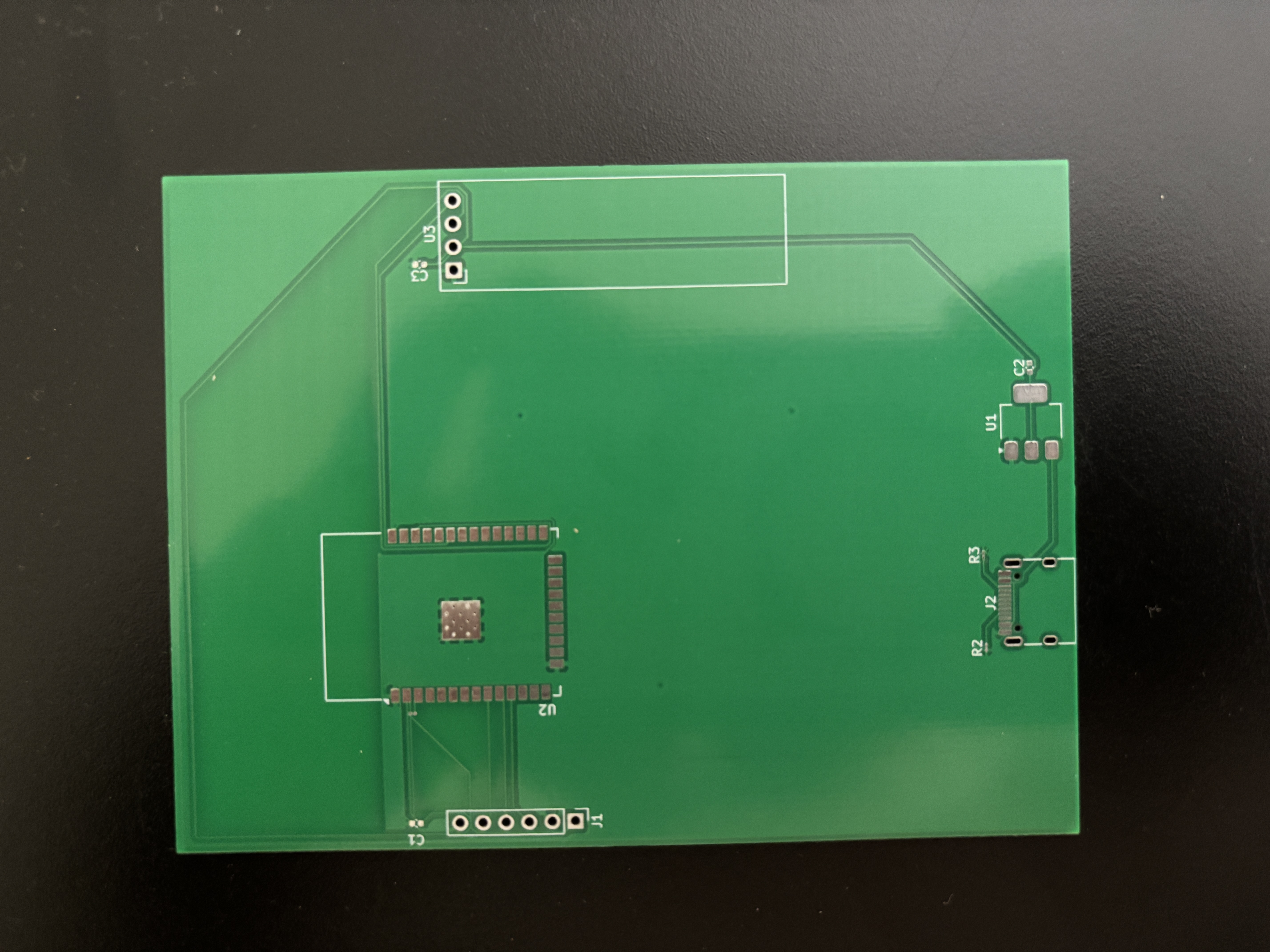
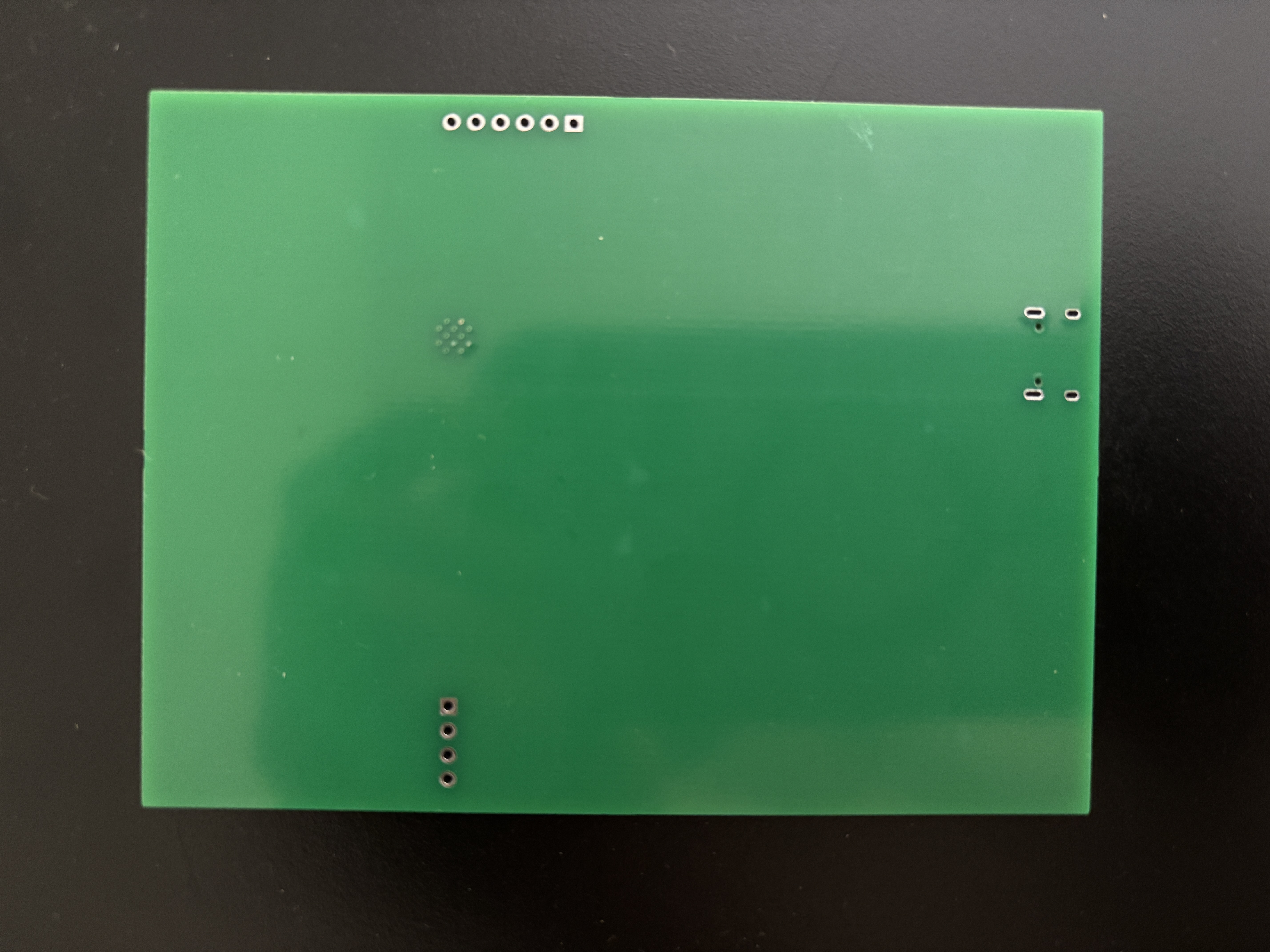
Spectrum analyzer is an open-source printed circuit board by JadenS180, from the JadenS180/spectrum-analyzer repository on GitHub, published under the MIT licence. It is a 2-layer board of 74.9 × 100.3 mm with 11 parts on 49 nets, routed with 126 tracks and 0 vias.
It is built around the ESP32-WROOM-32, AMS1117-3.3 and INMP441. Its parts include 3 capacitors, 3 resistors, 3 ICs and 2 connectors. It belongs with the sensors and measurement and audio and music boards and the ESP32 boards of this library.


A real-time audio spectrum analyzer built on the ESP32, featuring a custom-designed PCB. Captures audio via an I2S MEMS microphone, runs FFT processing on-chip, displays a live 16-bar frequency spectrum on an OLED display, and streams real-time FFT data over WiFi to a browser-based visualizer via WebSockets.
Analyzer reacting to noise:
https://github.com/JadenS180/spectrum-analyzer/raw/main/media/spectrum-DemoNoise.MOV
Analyzer in a quiet environment:
https://github.com/JadenS180/spectrum-analyzer/raw/main/media/spectrum-DemoQuiet.MOV
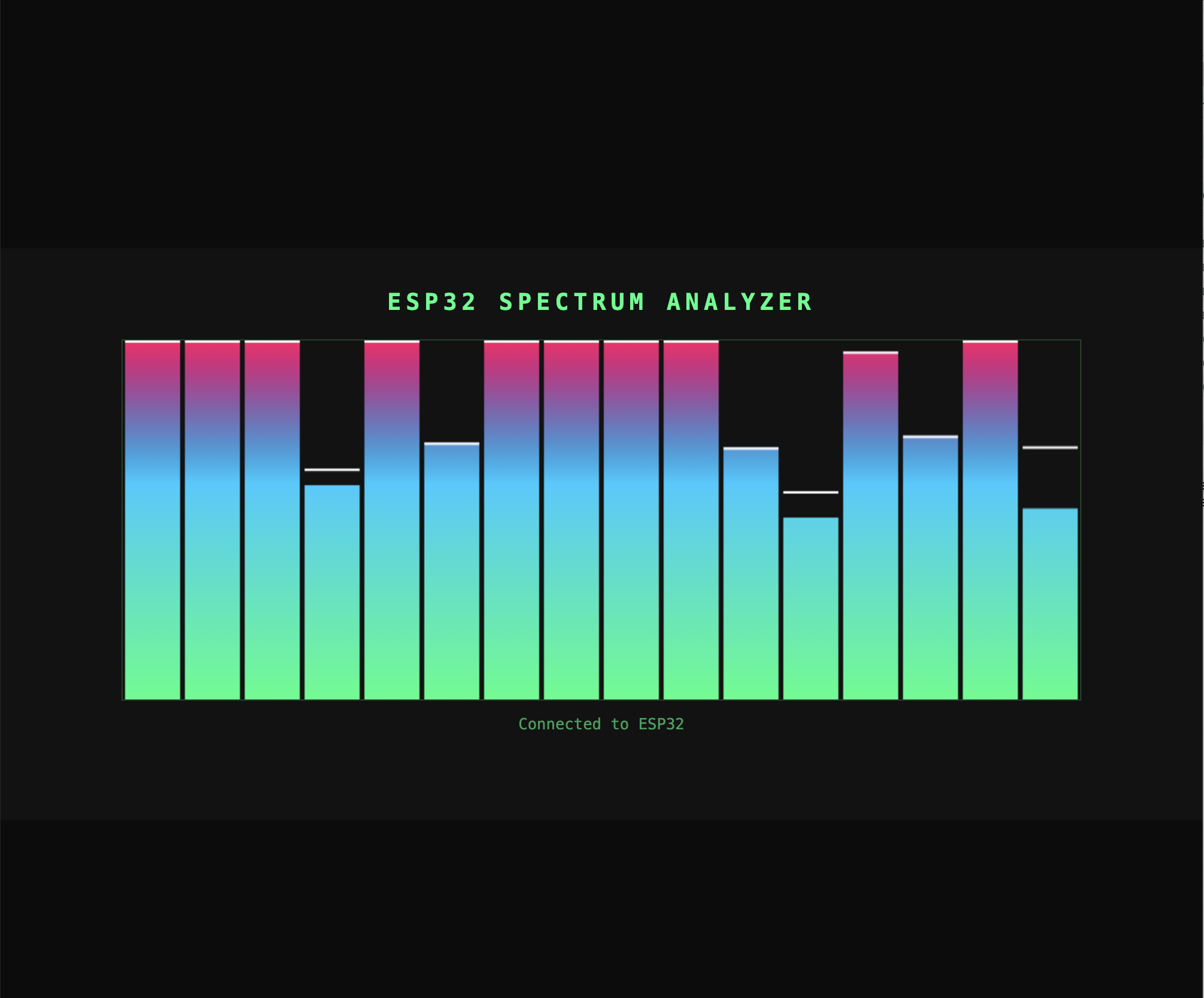
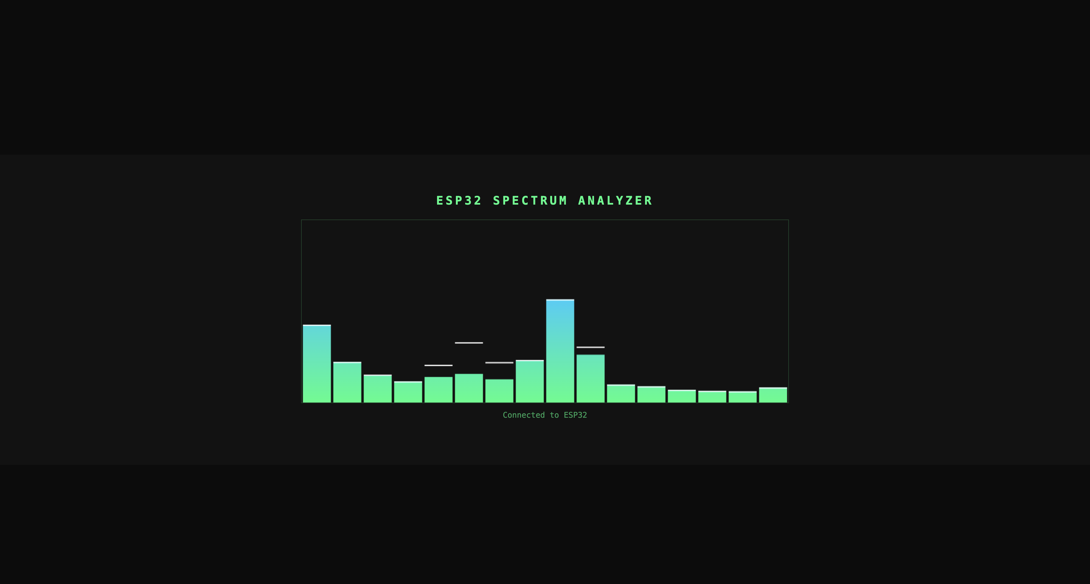
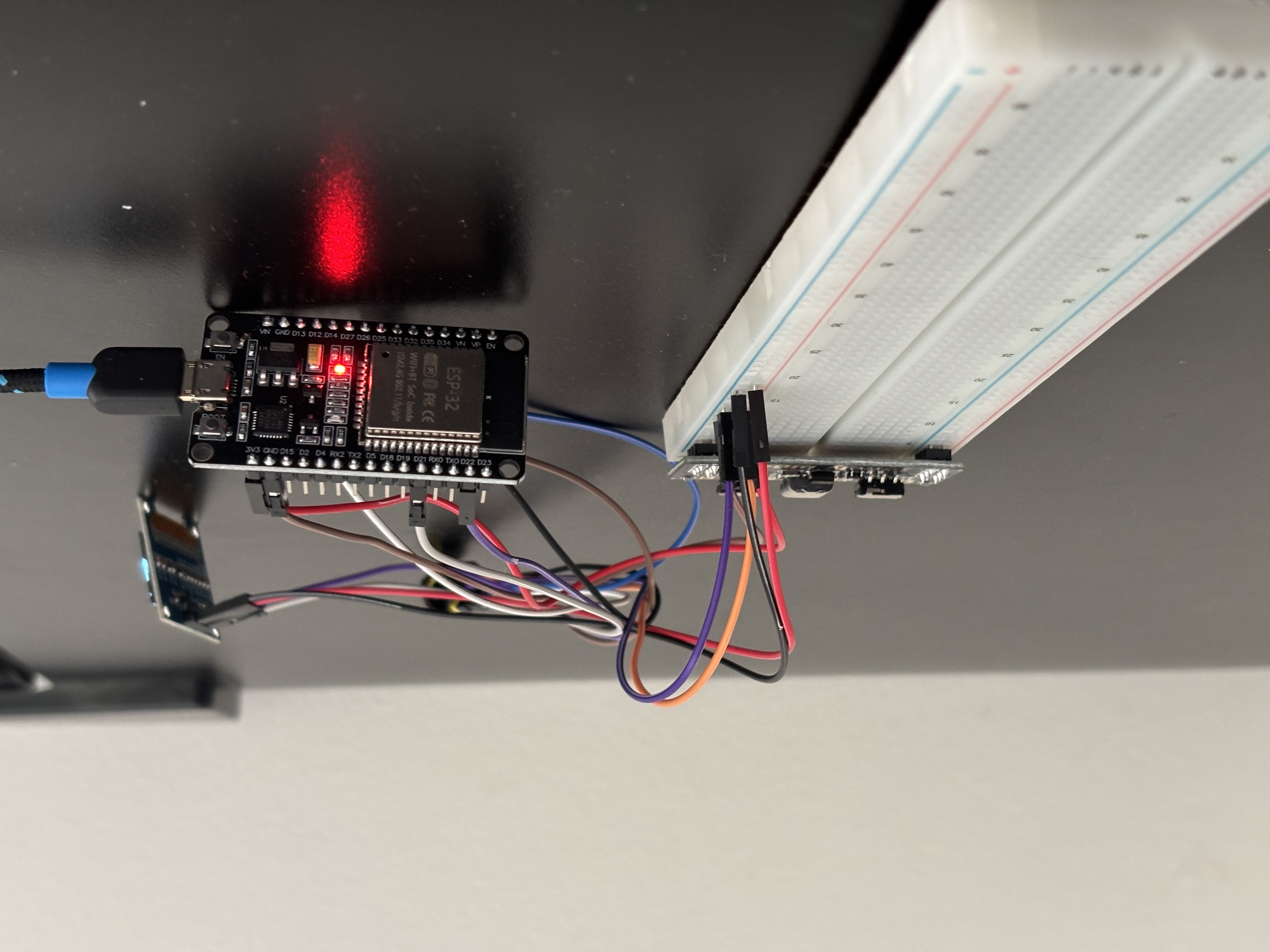
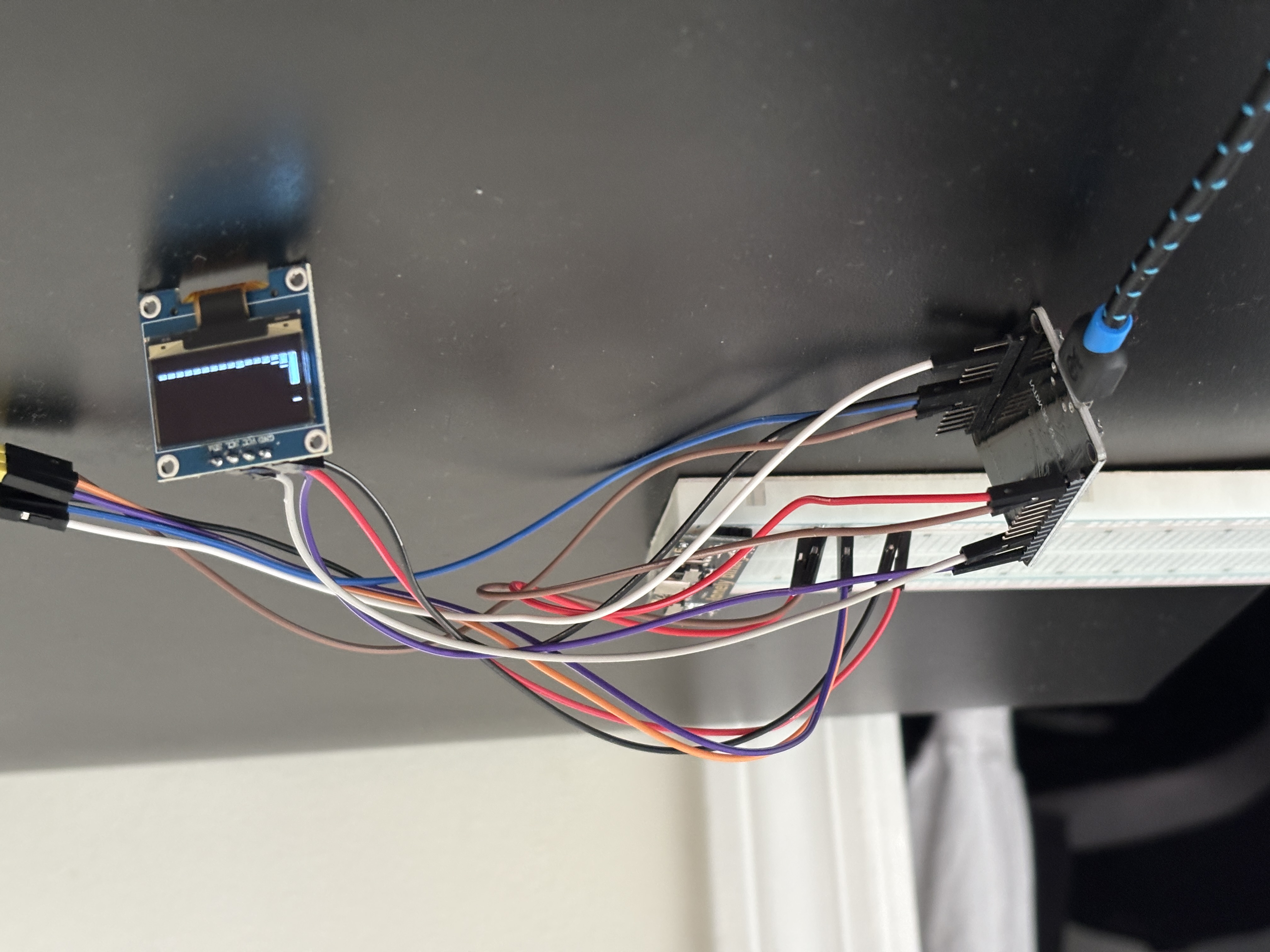
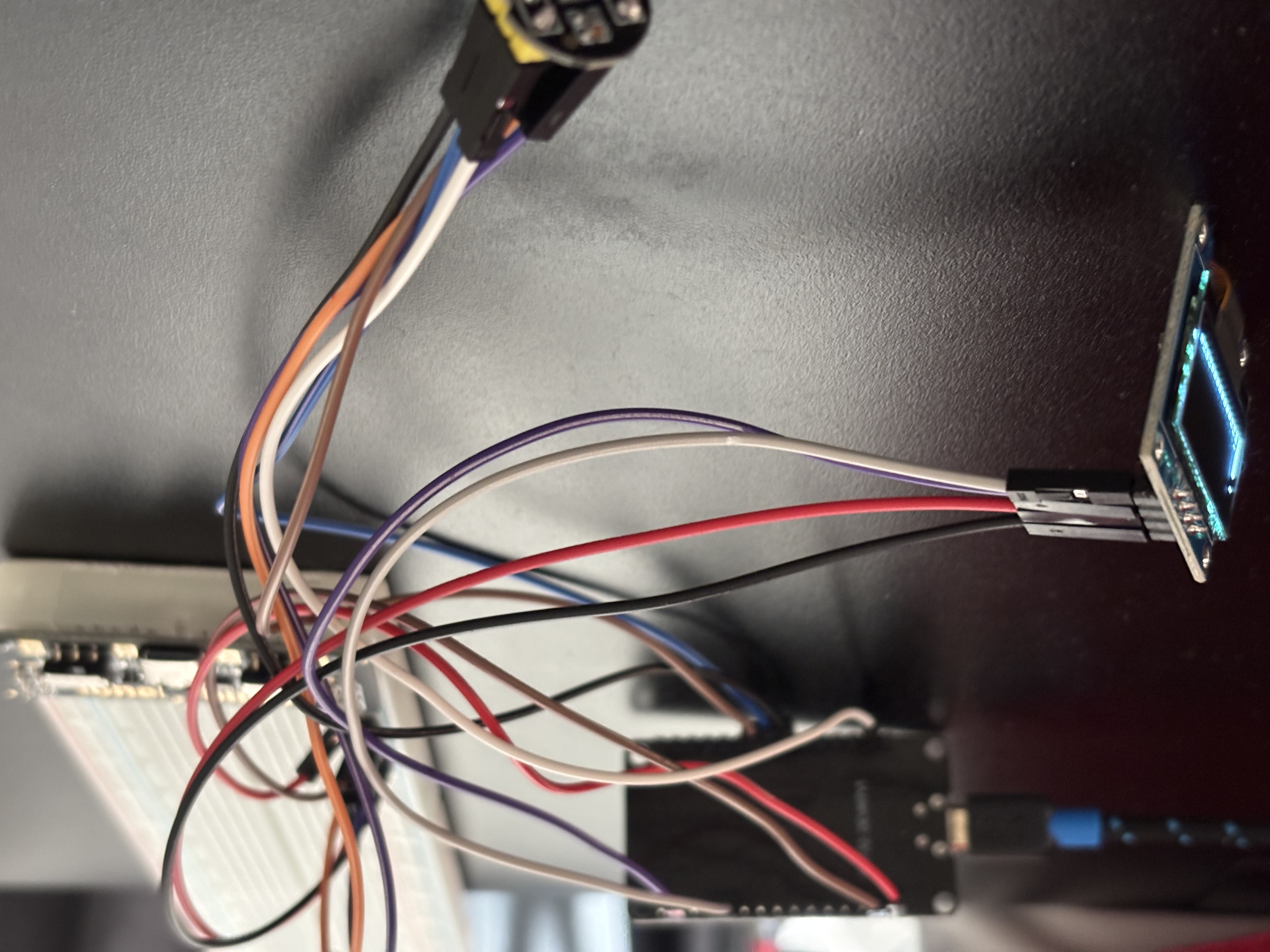
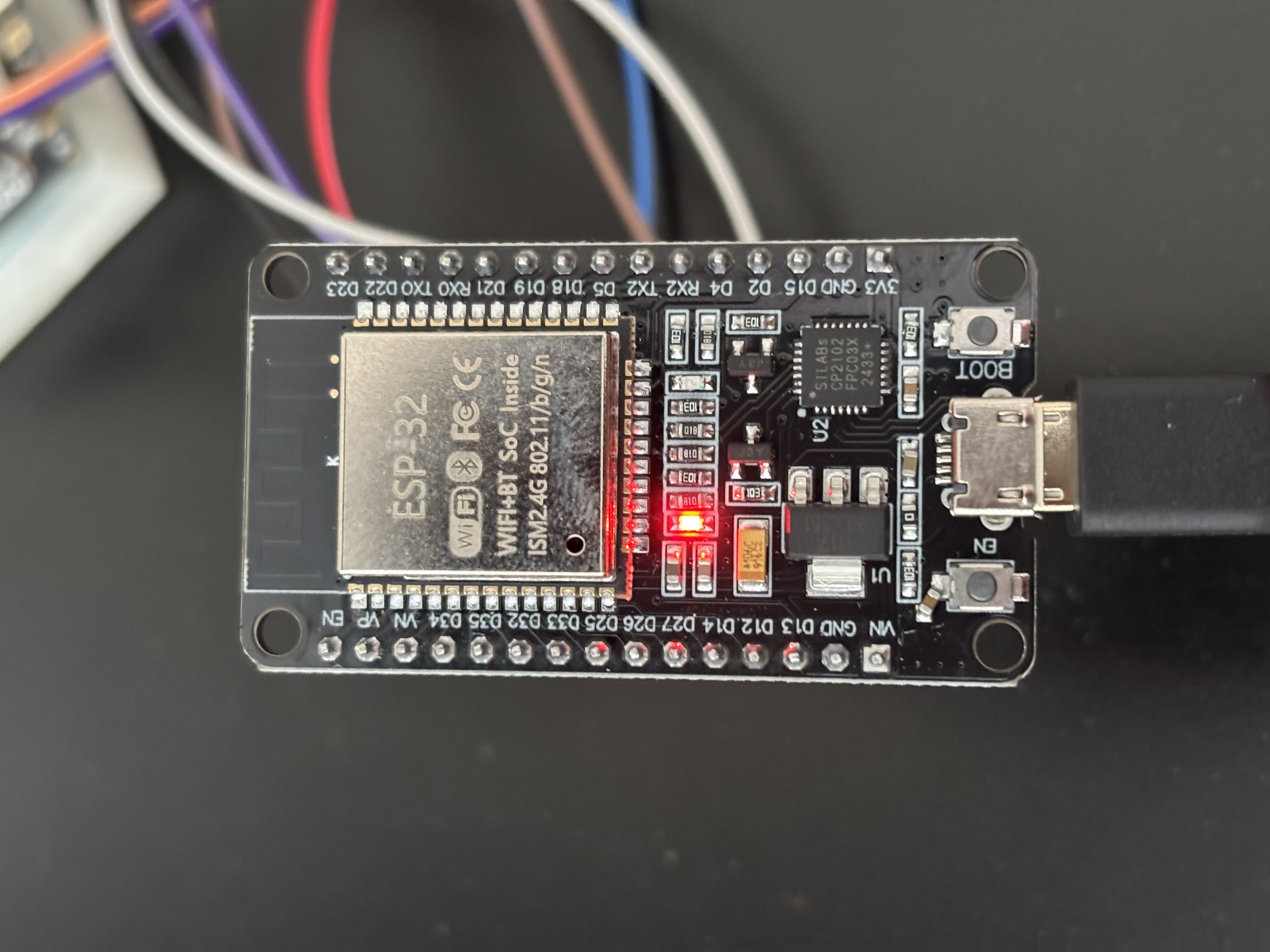 | 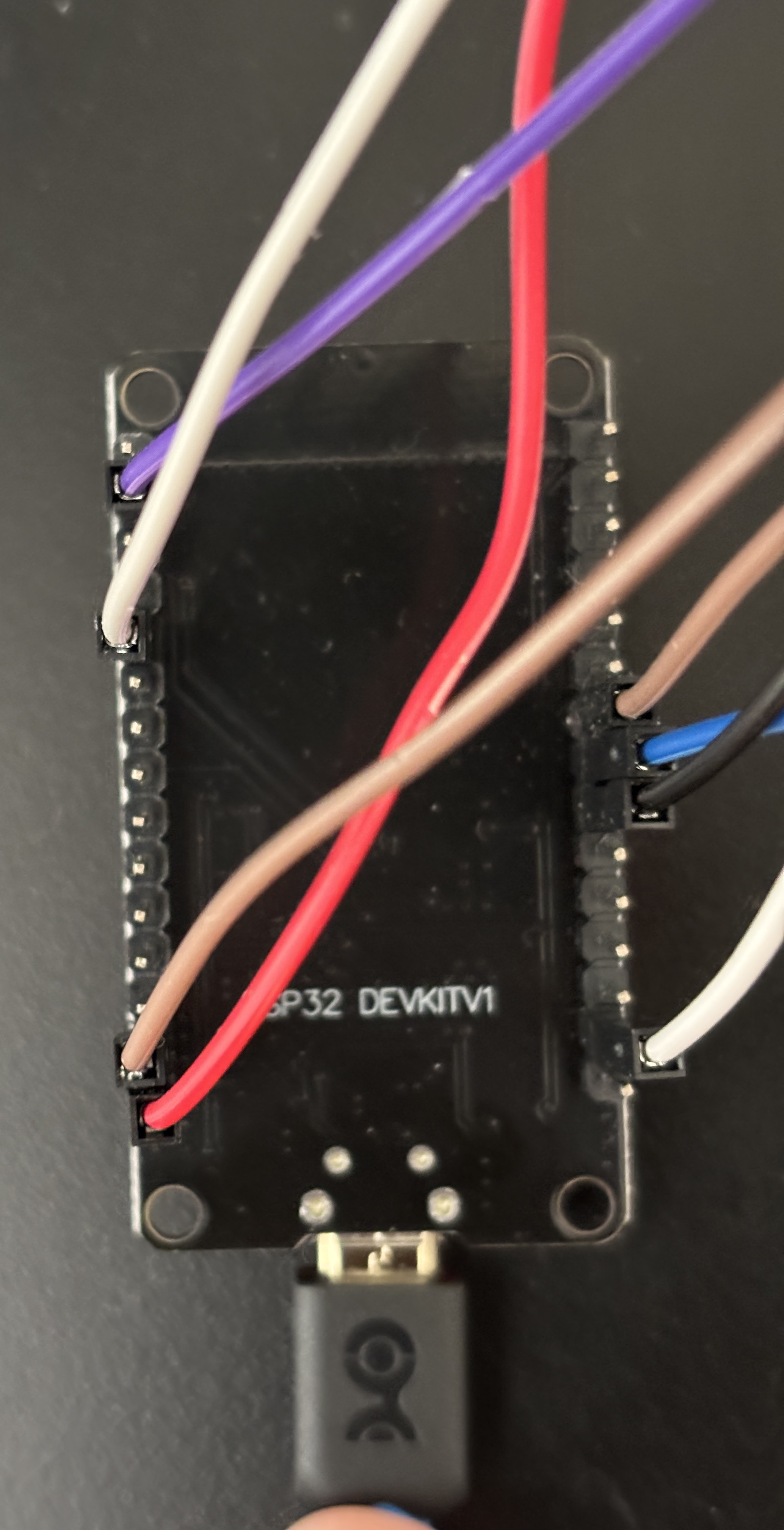 |
| ESP32-WROOM-32 (front) | ESP32-WROOM-32 (back) |
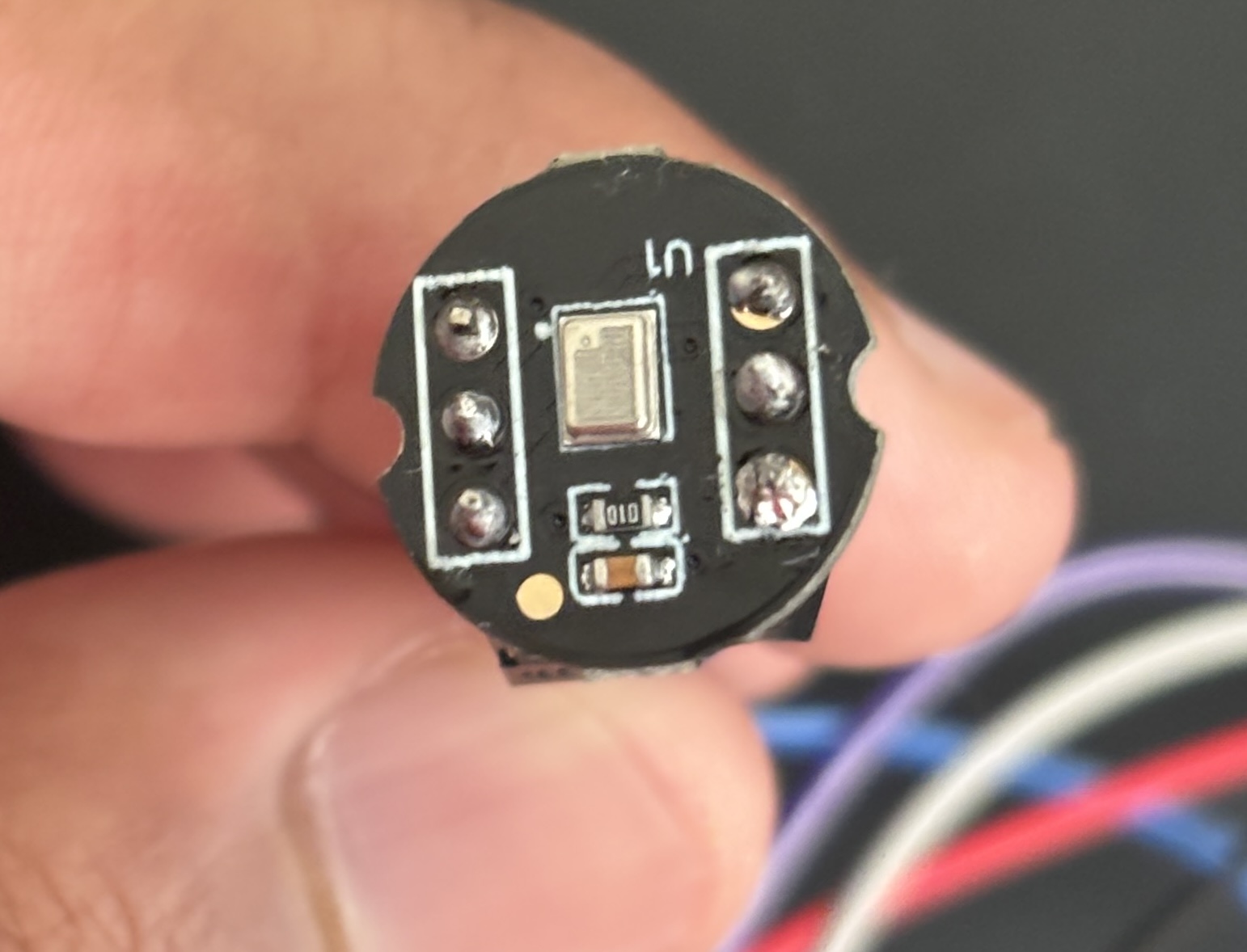 | 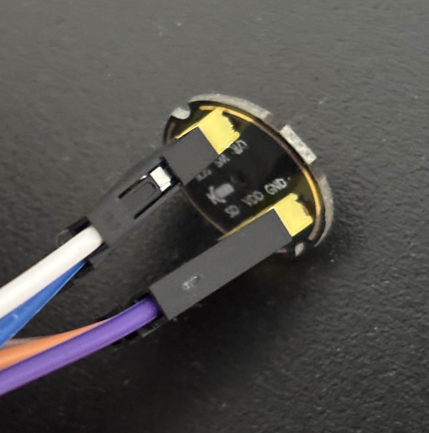 |
| INMP441 Microphone (front) | INMP441 Microphone (back) |
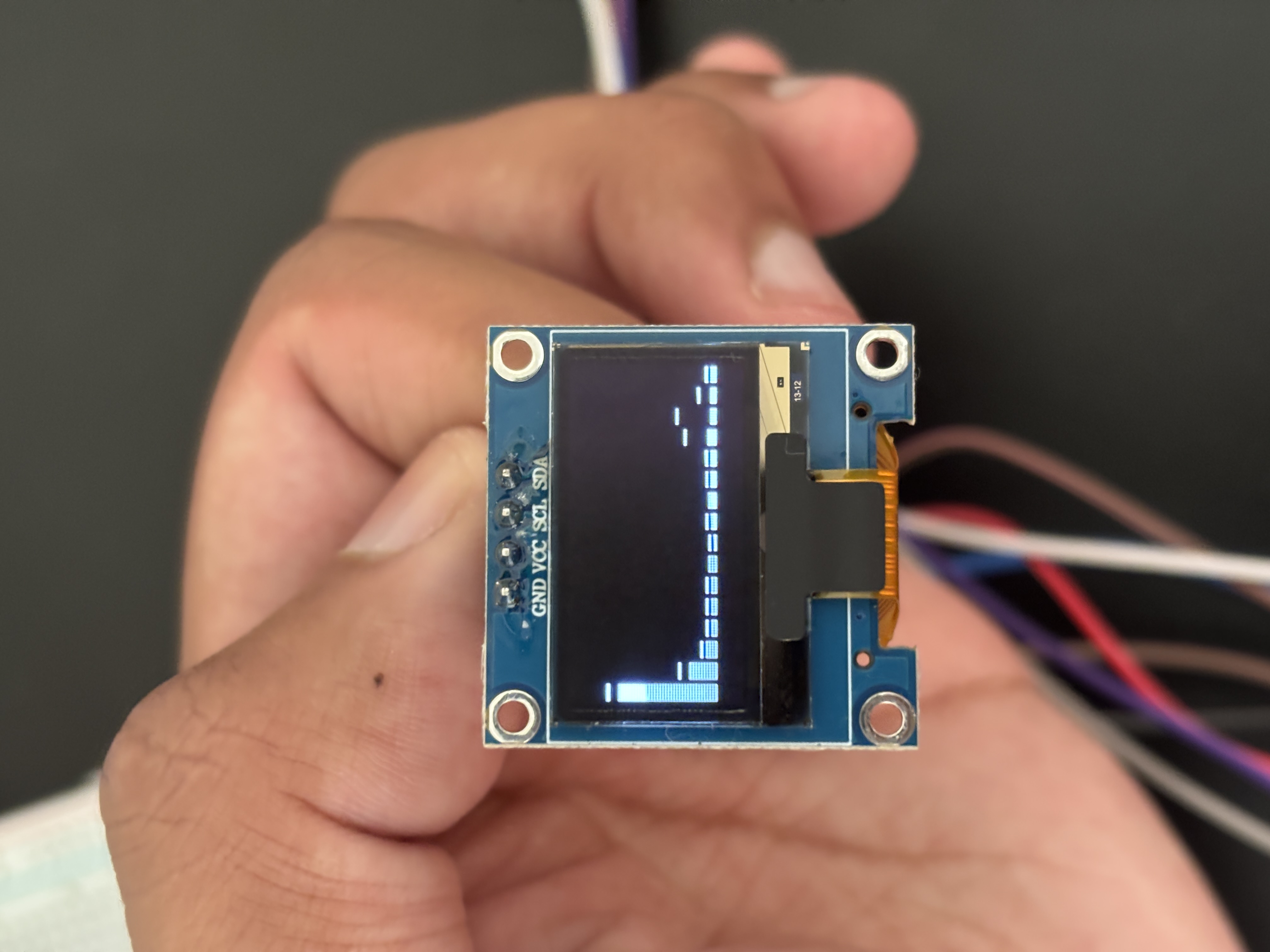 | 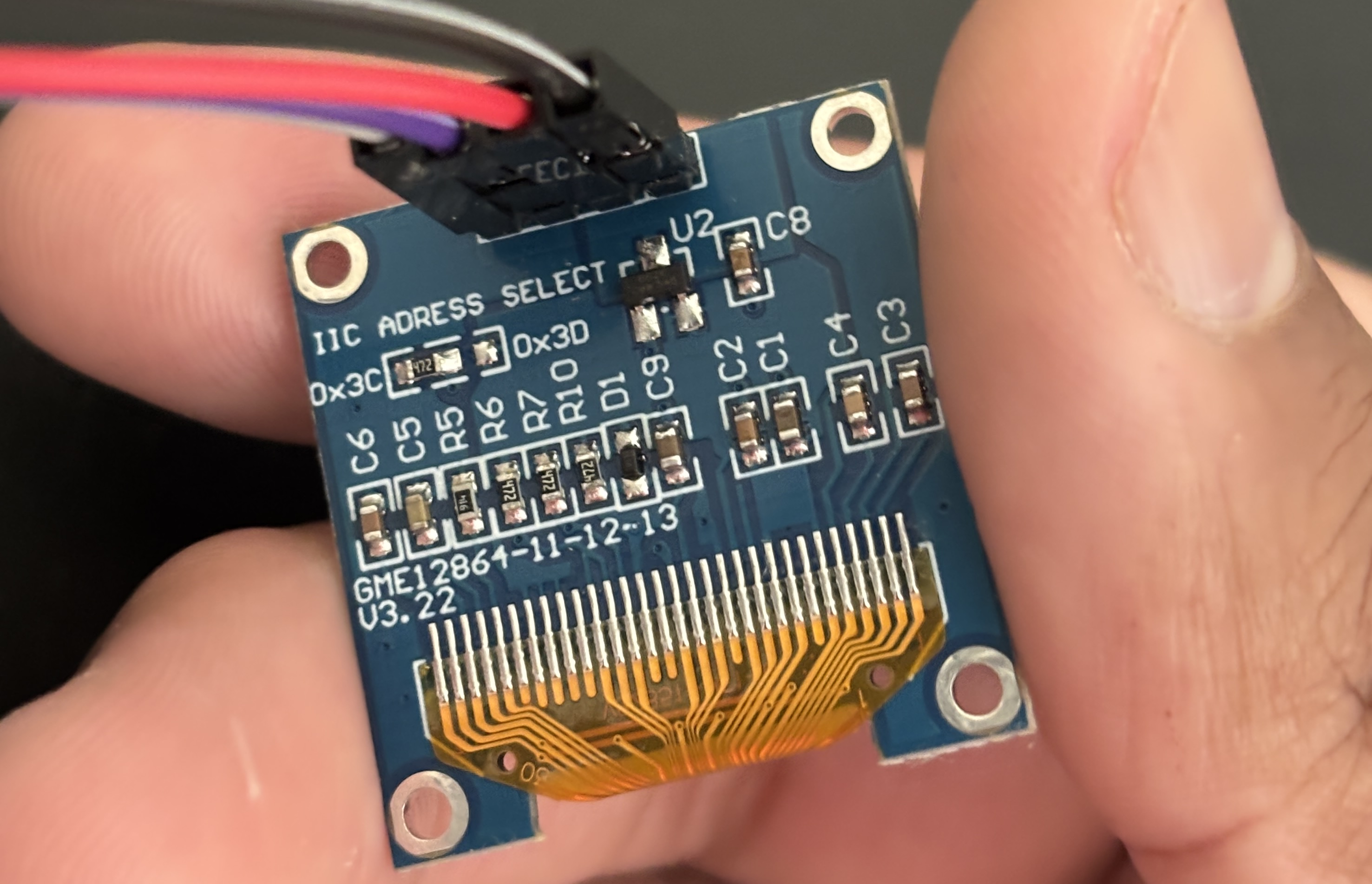 |
| SSD1306 OLED (front) | SSD1306 OLED (back) |
| Component | Description |
|---|---|
| ESP32-WROOM-32 | Microcontroller |
| INMP441 | I2S MEMS microphone |
| SSD1306 | 0.91" I2C OLED display (128x32) |
| AMS1117-3.3 | 3.3V LDO voltage regulator |
| USB-C Receptacle | Power input |
| Signal | ESP32 GPIO |
|---|---|
| I2S SCK | 26 |
| I2S WS | 25 |
| I2S SD | 33 |
| I2C SDA | 21 |
| I2C SCL | 22 |
Written in Arduino C++ using the Espressif ESP32 package (v3.3.10).
Dependencies:
To flash:
The dashboard is a single HTML file in the dashboard/ directory. Open it in a browser while the ESP32 is powered and connected to WiFi. Update the WebSocket IP in index.html to match your ESP32's IP address.
Designed in KiCad. The board is a 2-layer FR-4 PCB with a filled GND copper pour on F.Cu and a keep-out zone over the ESP32 antenna. Manufactured by JLCPCB.
KiCad schematic, PCB layout, and Gerber files are in the hardware/ directory.
spectrum-analyzer/
├── firmware/
│   └── spectrum_analyzer.ino
├── hardware/
│   ├── spectrum_analyzer.kicad_pro
│   ├── spectrum_analyzer.kicad_sch
│   ├── spectrum_analyzer.kicad_pcb
│   └── gerbers/
├── dashboard/
│   └── index.html
├── media/
│   ├── (photos)
│   └── (videos)
└── README.mdJaden Smiles — github.com/JadenS180
| Qty | Value | Footprint | References |
|---|---|---|---|
| 3 | 100n | Capacitor_SMD:C_0402_1005Metric | C1, C2, C3 |
| 2 | 5.1k | Resistor_SMD:R_01005_0402Metric | R2, R3 |
| 1 | 10k | Resistor_SMD:R_01005_0402Metric | R1 |
| 1 | AMS1117-3.3 | Package_TO_SOT_SMD:SOT-223-3_TabPin2 | U1 |
| 1 | ER_OLEDM0.91_1x-I2C | Display:ER_OLEDM0.91_1x-I2C | U3 |
| 1 | ESP32-WROOM-32 | RF_Module:ESP32-WROOM-32 | U2 |
| 1 | INMP441 | Connector_PinHeader_2.54mm:PinHeader_1x06_P2.54mm_Vertical | J1 |
| 1 | USB_C_Receptacle_USB2.0_16P | Connector_USB:USB_C_Receptacle_HRO_TYPE-C-31-M-12 | J2 |
It measures 74.9 × 100.3 mm and has 2 copper layers, 1.6 mm thick.
11 parts, built around the ESP32-WROOM-32, AMS1117-3.3 and INMP441. The full list of its parts is on this page, with links to each part's symbol and footprint where PCBKit's library has them.
From the JadenS180/spectrum-analyzer repository on GitHub, at the commit this page was made from: the board is hardware/spectrum_analyzer.kicad_pcb and its schematic hardware/spectrum_analyzer.kicad_sch. PCBKit opens the board in the browser, with nothing to install.
Its repository publishes it under the MIT licence: you may reuse it on that licence's terms (keep the author's notice, and for a copyleft licence share your changes alike).
galopago/iot-badge-legacy
Electronic conference badge for programming conventions, hacking events, etc.


Mohamedqweder/smart-ip-phone
Schaltplan und PCB-Design für ein WLAN-basiertes IP-Telefon. Entwickelt mit KiCad auf Basis des ESP32-WROOM-32.


Mounith-H/AI-Powered-Edge-Gunshot-Detection-for-Wildlife-Protection
Intelligent gunshot detection system using Raspberry Pi Pico


Hasenpups/WLED_ESP32_Controller
This work is licensed under a [Creative Commons Attribution-NonCommercial-ShareAlike 4.0 International License][cc-by-nc-sa].