

4 layers122.2 × 115.1 mm
Scan controller kicad
fwachsmuth/Filmkorn-Raw-Scanner
The Filmkorn Raw Scanner, turning 8mm and 16mm films into lossless 12-bit CinemaDNG
170 parts13MIT

 JackOLntrn/EMBER2
Fire Suppression System with thermal camera detection on a pan/tilt mechanism with house hold hose adaptor.
ME507-EMBER is an open-source printed circuit board by JackOLntrn, from the JackOLntrn/EMBER repository on GitHub, published under the MIT licence. It is a 2-layer board of 79.2 × 63.5 mm with 27 parts on 45 nets, routed with 172 tracks and 83 vias.
It is built around the DRV8871DDA and SVD5867NLT4G-UM. Its parts include 9 resistors, 6 connectors, 3 capacitors, 2 ICs and 1 diode.
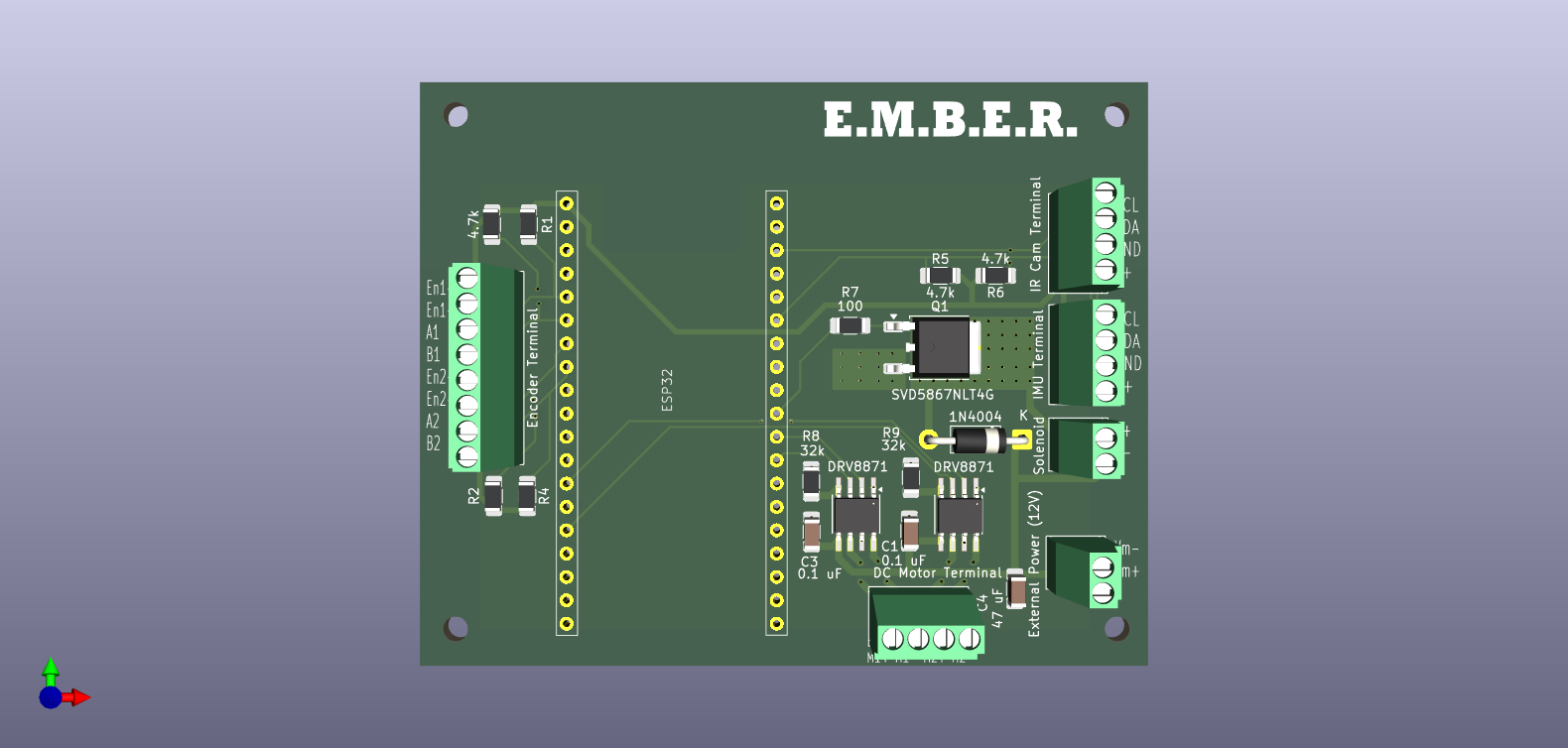
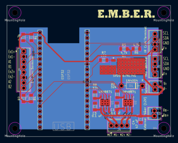
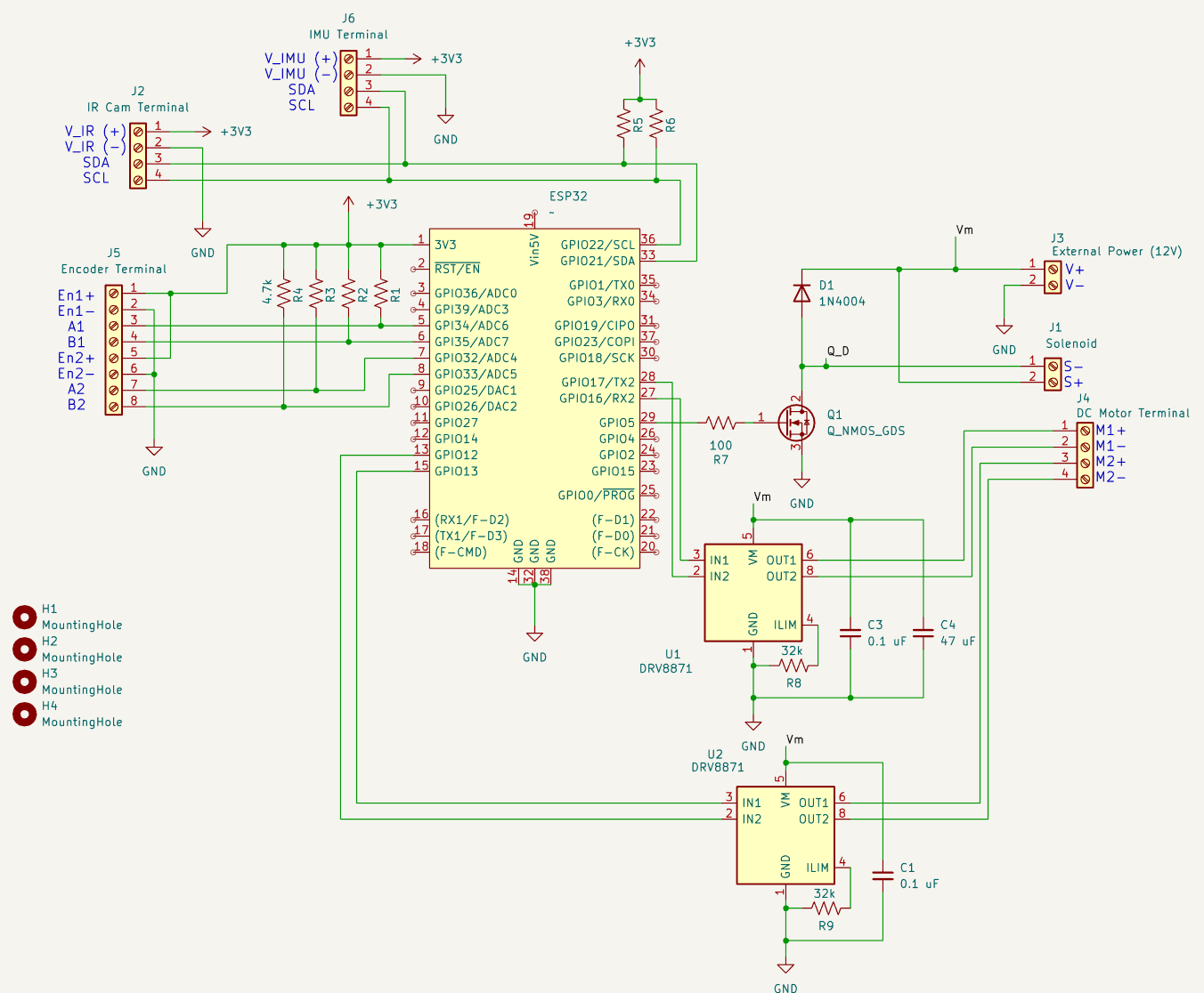
This folder contains the schematic and pcb files for EMBER.
The board has the following terminals for connection to hardware:
| Terminal | Description |
|---|---|
| ESP32 Pin Connector | 28 pin connector for connection of ESP32 to the board. |
| Encoder Terminal | 8 position terminal for connection to the 2 motor quadrature encoders. Has 3.3V+ and gnd output for both terminals denoted by Eni+ and Eni- respectively. Has inputs for channels A and B. |
| DC Motor Terminal | 4 position terminal to connect the 2 motors. Ensure that motor 1's encoder is connected to channels A1 and B1 on the encoder terminal, and motor 2's encoder is connected to channels A2 and B2 on the encoder terminal. |
| IR Cam Terminal | 4 position terminal for I2C connection to the MLX90640 Thermal IR Camera. Has 3.3V+ and gnd output and SDA/SCL input. |
| IMU Terminal | 4 position terminal to support an additional I2C peripheral, for instance an IMU. Has 3.3V+ and gnd output and SDA/SCL input. |
| Solenoid | 2 position terminal for connection to the Solenoid. Outputs Vm+ and Vm- using a MOSFET controlled by the microcontroller with a flyback diode circuit. |
| External Power (12V) | 2 position terminal for connection to battery. Vm+ should be ~12V+ and Vm- should be gnd. |
Main microcontroller for project - AliExpress: NodeMCU ESP-32S
Motor driver with 2 inputs from controller for PWM control - Texas Instruments: DRV8871DDAR
Flyback Diode for Solenoid/MOSFET circuit : 1N4004-E3/54
MOSFET to turn solenoid on/off from microcontroller N-Channel 60 V 22A (Tc) 3.3W (Ta), 43W (Tc) - Onsemi: SVD5867NLT4G
Resistor between microcontroller and MOSFET gate - Vishay Dale: TNPW1206100RBEEA
Pullup Resistors for I2C circuit and Encoder Channels - YAGEO: RC1206FR-074K7L
Current limit resistor for motor drivers (limitting to 2A, under the motor stall current to protect motors) - KOA Speer Electronics, Inc: RN73H2BTTD3202F100
Filter capacitor for motor drivers - TDK Corporation: C3216X5R1E476M160DC
Filter capacitor for motor drivers - KEMET: C1206C104K5RACTU
12V power in and Solenoid power out terminals - Phoenix Contact: 1725656
I2C connections (2 were added for potential to integrate another I2C peripheral such as an IMU, although only 1 is used for Thermal IR camera), and motor output connection - Phoenix Contact: 1725672
Encoder connections - Phoenix Contact: 1725711
| Qty | Value | Footprint | References |
|---|---|---|---|
| 4 | MountingHole | MountingHole:MountingHole_2.7mm_M2.5 | H1, H2, H3, H4 |
| 3 | 4.7k | Resistor_SMD:R_1206_3216Metric_Pad1.30x1.75mm_HandSolder | R4, R5, R6 |
| 3 | ~ | Resistor_SMD:R_1206_3216Metric_Pad1.30x1.75mm_HandSolder | R1, R2, R3 |
| 2 | 0.1 uF | Capacitor_SMD:C_1206_3216Metric_Pad1.33x1.80mm_HandSolder | C1, C3 |
| 2 | 32k | Resistor_SMD:R_1206_3216Metric_Pad1.30x1.75mm_HandSolder | R8, R9 |
| 2 | DRV8871 | Package_SO:Texas_HTSOP-8-1EP_3.9x4.9mm_P1.27mm_EP2.95x4.9mm_Mask2.4x3.1mm_ThermalVias | U1, U2 |
| 1 | 100 | Resistor_SMD:R_1206_3216Metric_Pad1.30x1.75mm_HandSolder | R7 |
| 1 | 1N4004 | Diode_THT:D_DO-41_SOD81_P10.16mm_Horizontal | D1 |
| 1 | 47 uF | Capacitor_SMD:C_1206_3216Metric_Pad1.33x1.80mm_HandSolder | C4 |
| 1 | DC Motor Terminal | TerminalBlock_Phoenix:TerminalBlock_Phoenix_MPT-0,5-4-2.54_1x04_P2.54mm_Horizontal | J4 |
| 1 | Encoder Terminal | TerminalBlock_Phoenix:TerminalBlock_Phoenix_MPT-0,5-8-2.54_1x08_P2.54mm_Horizontal | J5 |
| 1 | External Power (12V) | TerminalBlock_Phoenix:TerminalBlock_Phoenix_MPT-0,5-2-2.54_1x02_P2.54mm_Horizontal | J3 |
| 1 | IMU Terminal | TerminalBlock_Phoenix:TerminalBlock_Phoenix_MPT-0,5-4-2.54_1x04_P2.54mm_Horizontal | J6 |
| 1 | IR Cam Terminal | TerminalBlock_Phoenix:TerminalBlock_Phoenix_MPT-0,5-4-2.54_1x04_P2.54mm_Horizontal | J2 |
| 1 | SVD5867NLT4G | Package_TO_SOT_SMD:TO-252-2 | Q1 |
| 1 | Solenoid | TerminalBlock_Phoenix:TerminalBlock_Phoenix_MPT-0,5-2-2.54_1x02_P2.54mm_Horizontal | J1 |
| 1 | ~ | ME507F24:ESP32_NodeMCU_KeeYees | ESP32 |
It measures 79.2 × 63.5 mm and has 2 copper layers, 1.6 mm thick.
27 parts, built around the DRV8871DDA and SVD5867NLT4G-UM. The full list of its parts is on this page, with links to each part's symbol and footprint where PCBKit's library has them.
From the JackOLntrn/EMBER repository on GitHub, at the commit this page was made from: the board is hardware/board/ME507-EMBER.kicad_pcb and its schematic hardware/board/ME507-EMBER.kicad_sch. PCBKit opens the board in the browser, with nothing to install.
Its repository publishes it under the MIT licence: you may reuse it on that licence's terms (keep the author's notice, and for a copyleft licence share your changes alike).
fwachsmuth/Filmkorn-Raw-Scanner
The Filmkorn Raw Scanner, turning 8mm and 16mm films into lossless 12-bit CinemaDNG


AlessioMorale/unav2_hardware
Initial test hardware for the future uNav board version


