2 layers65 × 56 mm

 j1and1/HotPlate-controller3
Arduino based controller for heatplate. Intended for reflow operations
ControlBoard is an open-source printed circuit board by j1and1, from the j1and1/HotPlate-controller repository on GitHub. It is a 2-layer board of 84 × 45.3 mm with 23 parts on 20 nets, routed with 94 tracks and 10 vias.
Its parts include 9 resistors, 3 capacitors, 3 connectors, 3 switches and 1 IC.
This is still a work in progress, and controller code has issues of overshooting the target temperature use at your own risk.
This is a implementation of temperature control of heated plate for reflow soldering.
To make this you will need:
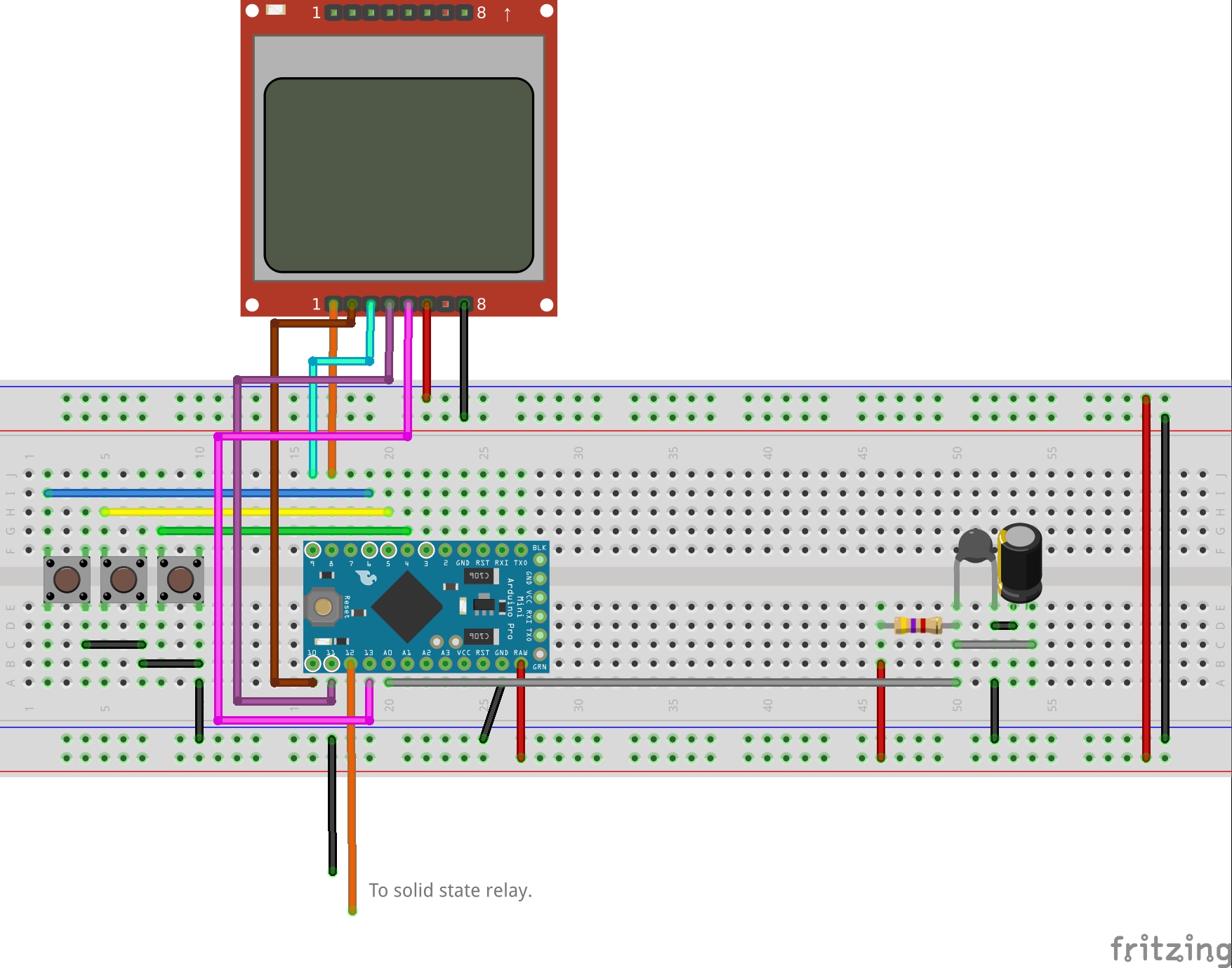
To compile Arduino code you will need few additional libraries.
| Qty | Value | Footprint | References |
|---|---|---|---|
| 5 | 10k | Resistor_SMD:R_01005_0402Metric_Pad0.57x0.30mm_HandSolder | R2, R3, R4, R7, R8 |
| 3 | SW_Push | Button_Switch_THT:SW_PUSH_6mm | SW1, SW2, SW3 |
| 2 | 100u | Capacitor_SMD:C_0603_1608Metric_Pad1.08x0.95mm_HandSolder | C2, C3 |
| 2 | Conn_01x02 | Connector_PinHeader_2.54mm:PinHeader_1x02_P2.54mm_Horizontal | J1, J2 |
| 1 | 10k | Resistor_SMD:R_0402_1005Metric_Pad0.72x0.64mm_HandSolder | R9 |
| 1 | 10uF | Capacitor_SMD:C_0603_1608Metric_Pad1.08x0.95mm_HandSolder | C1 |
| 1 | 1k | Resistor_SMD:R_01005_0402Metric_Pad0.57x0.30mm_HandSolder | R5 |
| 1 | 4.7k | Resistor_SMD:R_01005_0402Metric_Pad0.57x0.30mm_HandSolder | R1 |
| 1 | 440 | Resistor_SMD:R_01005_0402Metric_Pad0.57x0.30mm_HandSolder | R6 |
| 1 | Conn_01x13 | Connector_PinHeader_2.54mm:PinHeader_1x13_P2.54mm_Vertical | J3 |
| 1 | Nokia_5510_display_module | Nokia_5510_display_module:NOKIA_5510_display_module | U1 |
The 19 most common of 23 parts.
It measures 84 × 45.3 mm and has 2 copper layers, 1.6 mm thick.
23 parts. The full list of its parts is on this page, with links to each part's symbol and footprint where PCBKit's library has them.
From the j1and1/HotPlate-controller repository on GitHub, at the commit this page was made from: the board is PCB/ControlBoard.kicad_pcb. PCBKit opens the board in the browser, with nothing to install.
Its repository states no licence, so its author keeps all rights: ask j1and1 before reusing the design.

google/mozc-devices
Circuit diagrams and firmware source code for Gboard DIY keyboards


Duet3D/Duet-2-Hardware
The KiCAD source for the Duet 3d printer controller see www.duet3d.com