4 layers80 × 52.7 mm

 iustinG-afk/The48ErrCar
ESP32-S3-WROOM-1 RC car controller PCB with Wi-Fi app control (KiCad, ESP-IDF, MIT App Inventor)
The Big One is an open-source printed circuit board by iustinG-afk, from the iustinG-afk/The48ErrCar repository on GitHub, published under the MIT licence. It is a 2-layer board of 97.8 × 66.2 mm with 86 parts on 83 nets, routed with 524 tracks and 53 vias.
It is built around the ESP32-S3-WROOM-1-N8, TPS54331D and DRV8833PWP, with the AMS1117-1.5 among its other parts. Its parts include 24 resistors, 18 capacitors, 6 transistors, 5 ICs and 4 diodes. It belongs with the radio and wireless boards and the ESP32 boards of this library.


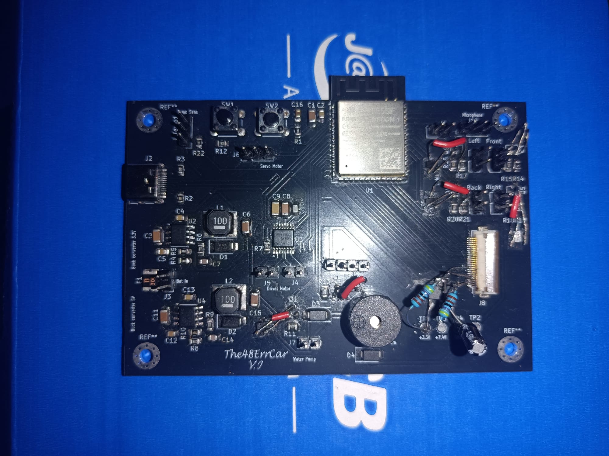
A custom-designed PCB that turns an RC car chassis into a Wi-Fi-controlled, sensor-equipped vehicle, driven from a mobile app built in MIT App Inventor.
I designed the board from scratch in KiCad, wrote the firmware in C (ESP-IDF) with the help of AI, hand-soldered every component, and built the control app. This was my first PCB project, so this repository also documents what went wrong and what I learned from it.
| Feature | Status | Notes |
|---|---|---|
| Forward / reverse drive | Working | PWM speed control through DRV8833 |
| Steering | Working | Servo driven by PWM |
| Front headlights | Working | N-MOS low-side switching |
| Brake / rear lights | Working | Automatically on when reversing or braking, with a manual override |
| Left / right turn signals | Working | Blinking at 500 ms |
| Horn / buzzer | Working | Hold-to-sound from the app |
| Water pump | Working | Low-side N-MOS switch with flyback diode |
| Temperature & humidity (DHT11) | Working | Read on demand from the app |
| Ultrasonic rear parking sensor | Working | Cuts reverse motor power at 5 cm or closer and beeps |
| Clap-controlled turn signals | Working, limited | Microphone detects volume spikes: 2 claps = left, 3 claps = right, 4 claps = hazard |
| Camera (OV3660, 24-pin FPC) | Not working | See Known issues |
                    2x 18650 (≅7.4 V)
                           |
                   [3A PTC polyfuse]
                           |
          +----------------+----------------+
          |                |                |
   Buck -> 3.3 V     Buck -> 5 V        Motor supply
   (TPS54331)        (TPS54331)           (7.4 V)
          |                |                |
   ESP32-S3, DHT11,   Servo, pump,       DRV8833
   mic, camera LDO    buzzer, US sensor   -> L / R motor pairs
          |
   ESP32-S3 (Wi-Fi AP + HTTP server)
          ^
          | HTTP over Wi-Fi
          |
   MIT App Inventor app (phone)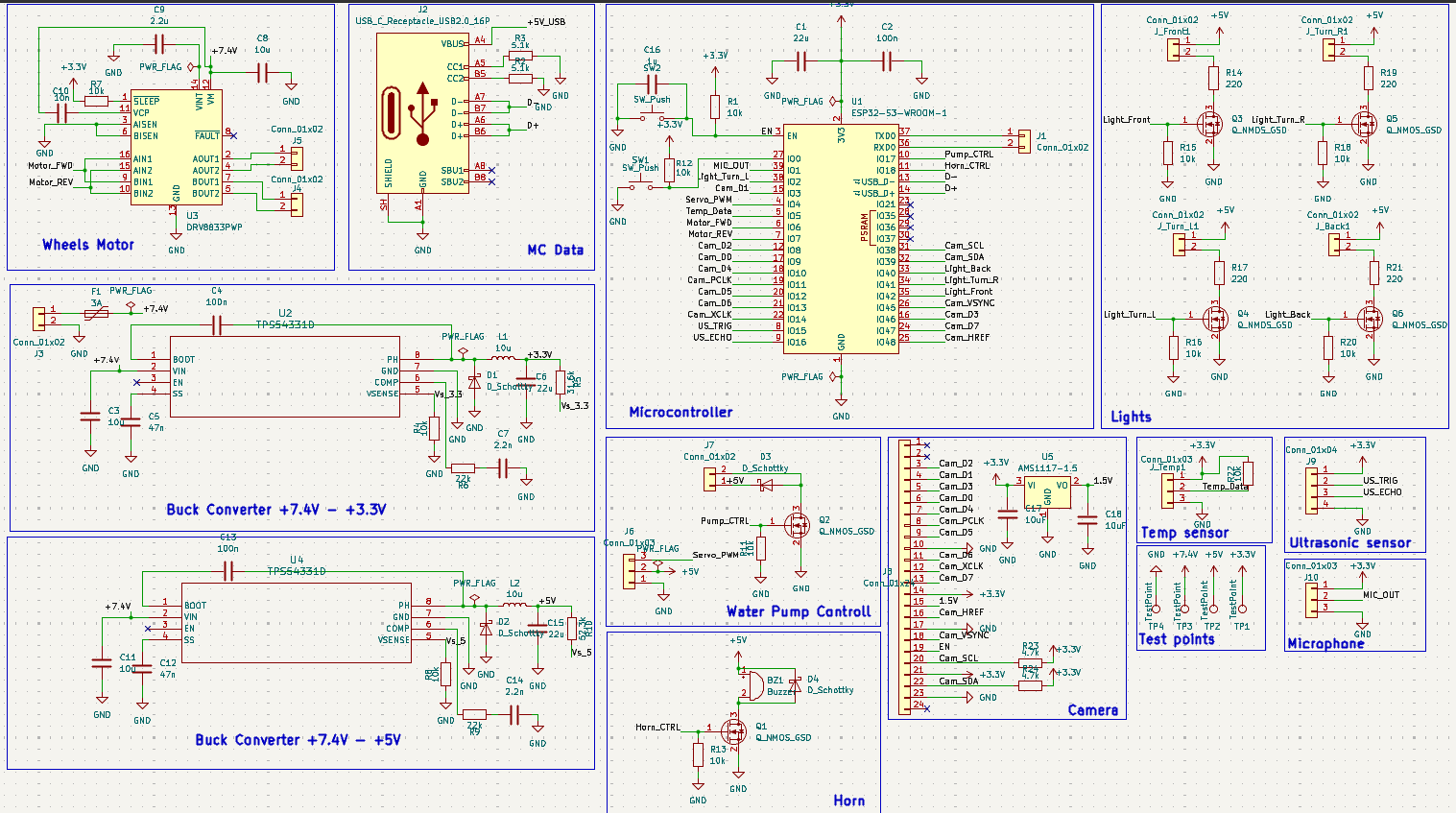
EN, pull-ups, and two buttons for reset and download modeWater pump, buzzer and four lights (front, rear, left and right signals) each use a logic-level N-MOSFET low-side switch with:
Sensors, motors, servo, microphone and lights connect through pin headers and jumper wires rather than being soldered to the board, so they can be mounted wherever they fit on the chassis.
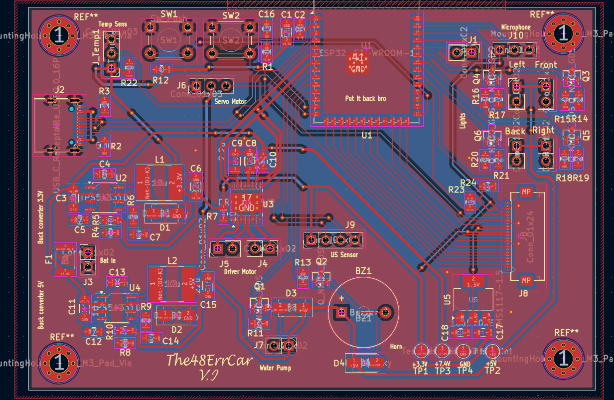
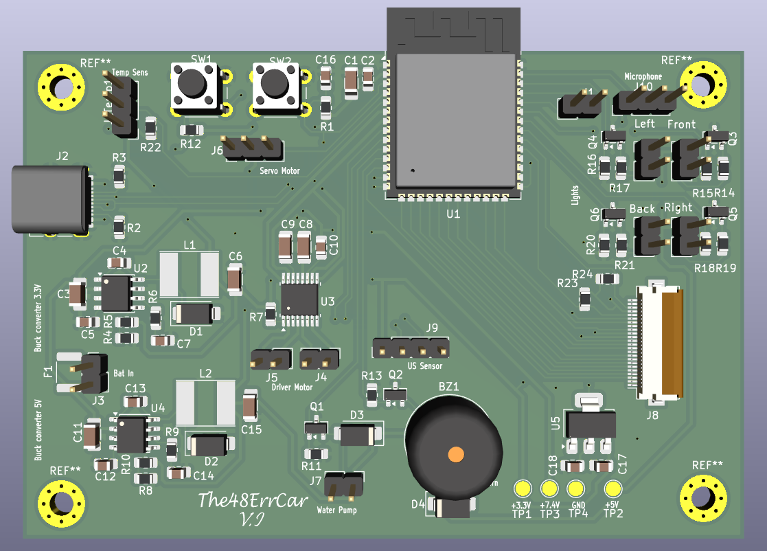
| PCB layout | 3D render |
|---|---|
 |  |
Written in C with ESP-IDF and FreeRTOS (main.c).
192.168.4.1)/cmd?c=... handles lights, signals, horn, pump, microphone mode and drive commands; /dht returns temperature and humidity/stream (disabled in practice because the camera hardware does not work, see below)Security note: the access point name and password are defined in
main.c. Change them before using the car anywhere other than your desk.
Built in MIT App Inventor (block-based). The app:
/cmd?c=ping)| Start | Credits |
|---|---|
 |  |
The App Inventor block screenshots are in MIT/.
V1 (fabricated and assembled)
V2 (current layout in this repository)
V3 (through-hole version)
| Schematic | PCB layout | 3D render |
|---|---|---|
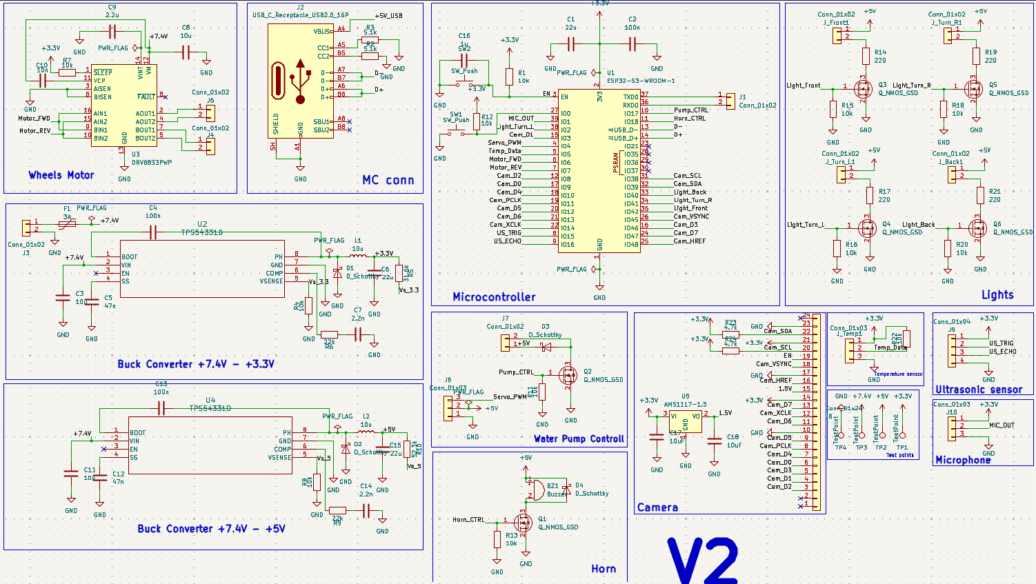 | 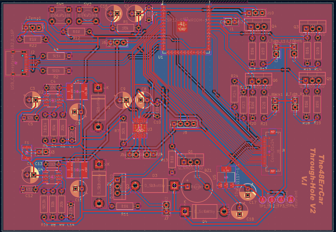 | 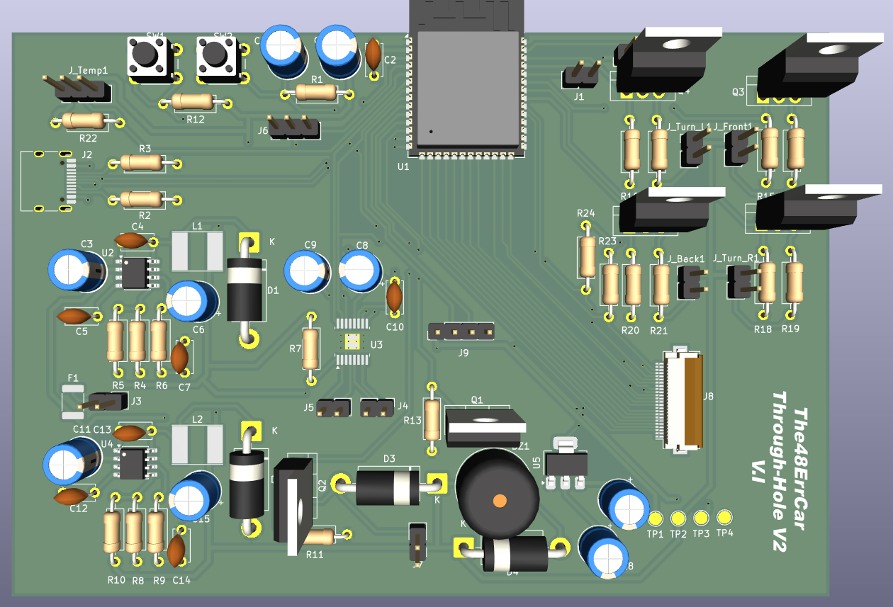 |
This was my first PCB, and I would rather document the mistakes honestly than hide them:
| Qty | Part |
|---|---|
| 1 | ESP32-S3-WROOM-1 |
| 2 | TPS54331D buck converter (SOIC-8) |
| 1 | DRV8833PWP motor driver (HTSSOP-16) |
| 1 | AMS1117-1.5 LDO (V2) |
| 6 | N-channel MOSFET (SOT-23) |
| 4 | Schottky diode (SMA) |
| 2 | 10 µH inductor |
| 1 | 3 A PTC resettable fuse |
| 1 | USB-C receptacle |
| 1 | 24-pin 0.5 mm FPC connector |
| 22 | 0805 resistors |
| 9 / 7 | 0805 / 1206 capacitors |
| 2 | Tactile push buttons |
| 1 | Buzzer |
| - | Pin headers |
Off-board: DC motors, servo, DHT11, HC-SR04-style ultrasonic sensor, microphone module, water pump, LEDs, 2x 18650 cells.
.
|-- docs/      images, gifs, documentation
|-- Through-hole/     KiCad project, schematic, layout V2
|-- MIT/           MIT App Inventor project pictures, videos, logo
|-- The48ErrCar.apk      Apk to download the app
|-- firmware.c/          ESP-32 Code
|-- hardware.c/ KiCad project, schematic, layoutThe board was assembled entirely by hand with a soldering iron and a heat gun.
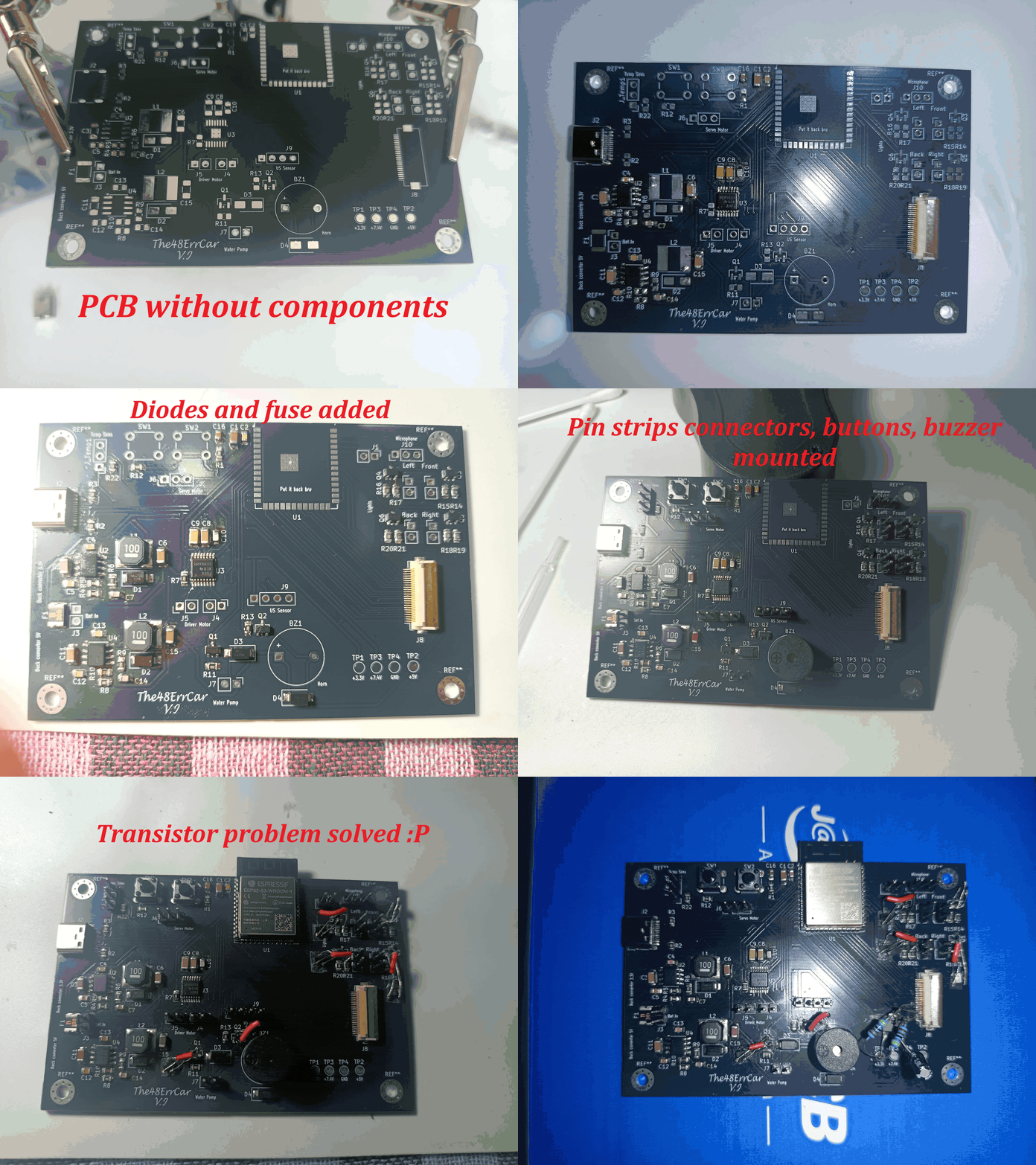
The board, firmware and app work together. The car was not assembled onto a chassis: my focus was the PCB design, schematic and firmware, so mounting is left as a DIY step.
| Qty | Value | Footprint | References |
|---|---|---|---|
| 12 | 10k | Resistor_SMD:R_0805_2012Metric_Pad1.20x1.40mm_HandSolder | R1, R4, R7, R8, R11, R12, R13, R15, R16, R18, R20, R22 |
| 9 | Conn_01x02 | Connector_PinHeader_2.54mm:PinHeader_1x02_P2.54mm_Vertical | Back, Front, J1, J3, J4, J5, J7, Left, Right |
| 6 | Q_NMOS_GDS | Package_TO_SOT_SMD:SOT-23 | Q1, Q2, Q3, Q4, Q5, Q6 |
| 4 | 220 | Resistor_SMD:R_0805_2012Metric_Pad1.20x1.40mm_HandSolder | R14, R17, R19, R21 |
| 4 | D_Schottky | Diode_SMD:D_SMA | D1, D2, D3, D4 |
| 4 | TestPoint | TestPoint:TestPoint_Pad_D2.0mm | TP1, TP2, TP3, TP4 |
| 3 | 100n | Capacitor_SMD:C_0805_2012Metric_Pad1.18x1.45mm_HandSolder | C2, C4, C13 |
| 3 | 10u | Capacitor_SMD:C_1206_3216Metric_Pad1.33x1.80mm_HandSolder | C3, C8, C11 |
| 3 | 22u | Capacitor_SMD:C_1206_3216Metric_Pad1.33x1.80mm_HandSolder | C1, C6, C15 |
| 3 | Conn_01x03 | Connector_PinHeader_2.54mm:PinHeader_1x03_P2.54mm_Vertical | J_Temp1, J6, J10 |
| 2 | 10u | Inductor_SMD:L_Taiyo-Yuden_NR-60xx_HandSoldering | L1, L2 |
| 2 | 10uF | Capacitor_SMD:C_0805_2012Metric_Pad1.18x1.45mm_HandSolder | C17, C18 |
| 2 | 2.2n | Capacitor_SMD:C_0805_2012Metric_Pad1.18x1.45mm_HandSolder | C7, C14 |
| 2 | 22k | Resistor_SMD:R_0805_2012Metric_Pad1.20x1.40mm_HandSolder | R6, R9 |
| 2 | 4.7k | Resistor_SMD:R_0805_2012Metric_Pad1.20x1.40mm_HandSolder | R23, R24 |
| 2 | 47n | Capacitor_SMD:C_0805_2012Metric_Pad1.18x1.45mm_HandSolder | C5, C12 |
| 2 | 5.1k | Resistor_SMD:R_0805_2012Metric_Pad1.20x1.40mm_HandSolder | R2, R3 |
| 2 | SW_Push | Button_Switch_THT:SW_PUSH_6mm_H5mm | SW1, SW2 |
| 2 | TPS54331D | Package_SO:SOIC-8_3.9x4.9mm_P1.27mm | U2, U4 |
| 1 | 10n | Capacitor_SMD:C_0805_2012Metric_Pad1.18x1.45mm_HandSolder | C10 |
| 1 | 1u | Capacitor_SMD:C_0805_2012Metric_Pad1.18x1.45mm_HandSolder | C16 |
| 1 | 2.2u | Capacitor_SMD:C_1206_3216Metric_Pad1.33x1.80mm_HandSolder | C9 |
| 1 | 31.6k | Resistor_SMD:R_0805_2012Metric_Pad1.20x1.40mm_HandSolder | R5 |
| 1 | 3A | Fuse:Fuse_1812_4532Metric | F1 |
| 1 | 52.3k | Resistor_SMD:R_0805_2012Metric_Pad1.20x1.40mm_HandSolder | R10 |
| 1 | AMS1117-1.5 | Package_TO_SOT_SMD:SOT-223-3_TabPin2 | U5 |
| 1 | Buzzer | Buzzer_Beeper:Buzzer_12x9.5RM7.6 | BZ1 |
| 1 | Conn_01x04 | Connector_PinHeader_2.54mm:PinHeader_1x04_P2.54mm_Vertical | J9 |
| 1 | Conn_01x24 | Connector_FFC-FPC:Hirose_FH12-24S-0.5SH_1x24-1MP_P0.50mm_Horizontal | J8 |
| 1 | DRV8833PWP | Package_SO:HTSSOP-16-1EP_4.4x5mm_P0.65mm_EP3.4x5mm_Mask2.46x2.31mm_ThermalVias | U3 |
| 1 | ESP32-S3-WROOM-1 | RF_Module:ESP32-S3-WROOM-1 | U1 |
| 1 | USB_C_Receptacle_USB2.0_16P | Connector_USB:USB_C_Receptacle_HRO_TYPE-C-31-M-12 | J2 |
The 82 most common of 86 parts.


prasannan-robots/Energy-Management-using-Surveillance-Camera
This is a project which uses camera to detect the humans and control indoor appliances


arcticlula/Netscore
Device that keeps track of a volleyball's game score (points and sets). Ideally it should be mounted on the net, since it has a display on the front and back and buttons on the sides.

HelloAlex4/Maturitaetsarbeit-Design-and-Development-of-a-Portable-Stereoscopic-Wigglegram-Camera
Documentation of the merged wigglegram camera


juicykinklabs/TongueTyper
A talking-gag that acts as a game controller, posture trainer, speaker, and more.
It measures 97.8 × 66.2 mm and has 2 copper layers, 1.6 mm thick.
86 parts, built around the ESP32-S3-WROOM-1-N8, TPS54331D, DRV8833PWP and AMS1117-1.5. The full list of its parts is on this page, with links to each part's symbol and footprint where PCBKit's library has them.
From the iustinG-afk/The48ErrCar repository on GitHub, at the commit this page was made from: the board is hardware/The Big One.kicad_pcb and its schematic hardware/The Big One.kicad_sch. PCBKit opens the board in the browser, with nothing to install.
Its repository publishes it under the MIT licence: you may reuse it on that licence's terms (keep the author's notice, and for a copyleft licence share your changes alike).