2 layers341.7 × 195.5 mm
VesselV3
Hy-5/VesselV3
Custom "Vessel" Keyboard - PCB + 3D Case Model + Firmware + Keycaps vector
382 partsMIT
 itzandroidtab/totp8
Hardware 2FA TOTP authenticator
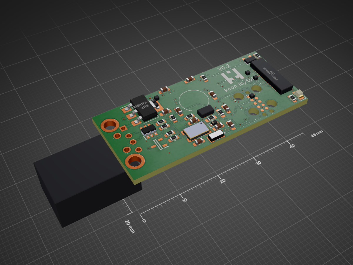
Lpc1756 totp is an open-source printed circuit board by itzandroidtab, from the itzandroidtab/totp repository on GitHub. It is a 2-layer board of 45 × 20 mm with 52 parts on 93 nets, routed with 415 tracks and 70 vias.
It is built around the AMS1117-3.3, PTS810SJK250SMTRLFS and ABM3B-12.000MHZ-B2-T, with the ABS07-32.768KHZ-T, BC856A,215-JSM and IP4234CZ6,125(ES) among its other parts. Its parts include 14 resistors, 10 capacitors, 4 ICs, 3 diodes and 3 switches. It belongs with the NXP (LPC, Kinetis, i.MX RT) boards of this library.


Open source hardware TOTP token. Currently targets the LPC1756, LPC1758 and LPC1759 (with a small change it should also run on the LPC1754).
Images can be found in the project logs at hackaday
TOTP uses klib. This repo can be cloned in the klib project folder. See build.yml for more info on compiling this project.
Is intended to be used with USB dfu bootloader. To build without bootloader support remove the + 8k and - 8k from line 20 in the linkerscript.ld of this project.
The LPC1756 does not have enough ram to hold a full framebuffer (240 * 135 * 2 = 64'800 bytes). To work around this issue, we use 2 smaller framebuffers we alternate between. While one framebuffer is being transferred to the screen using DMA we fill the other.
To make it easier (for me) the whole screen is written to this smaller framebuffer. The pixels that do not fit the framebuffer are thrown away. This does waste CPU cycles but is not limiting the framerate. Filling a full frame with pixels takes around 6 milliseconds. Writing a full frame of framebuffers to the display takes around 11 milliseconds. This limits the maximum framerate to ≈ 85FPS. To get a consistant frame rate there is a limit of 60FPS.
The main screen takes the longest to draw. This is caused by the amount of pixels of the circle it needs to draw. The circle is generated on compile time to work around that the LPC175x family does not have a FPU. These generated pixels use 8640 bytes of flash.
| Qty | Value | Footprint | References |
|---|---|---|---|
| 6 | , , , , , | ||
| 4 | 100nF | Capacitor_SMD:C_0603_1608Metric_Pad1.08x0.95mm_HandSolder | C7, C8, C9, C10 |
| 4 | 18pF | Capacitor_SMD:C_0603_1608Metric_Pad1.08x0.95mm_HandSolder | C3, C4, C5, C6 |
| 4 | 1k | Resistor_SMD:R_0603_1608Metric | R9, R11, R13, R14 |
| 3 | PTS810SJK250SMTRLFS | _SamacSys:PTS810SJG250SMTRLFS | S1, S2, S3 |
| 2 | 10uF | Capacitor_SMD:C_0603_1608Metric_Pad1.08x0.95mm_HandSolder | C1, C2 |
| 2 | 300 | Resistor_SMD:R_0603_1608Metric | R3, R6 |
| 2 | 33 | Resistor_SMD:R_0603_1608Metric | R1, R2 |
| 1 | 1.5K | Resistor_SMD:R_0603_1608Metric | R8 |
| 1 | 1.8K | Resistor_SMD:R_0603_1608Metric_Pad0.98x0.95mm_HandSolder | R12 |
| 1 | 1000 | Resistor_SMD:R_0603_1608Metric | R5 |
| 1 | 10K | Resistor_SMD:R_0603_1608Metric_Pad0.98x0.95mm_HandSolder | R10 |
| 1 | 1K | Resistor_SMD:R_0603_1608Metric | R7 |
| 1 | 750 | Resistor_SMD:R_0603_1608Metric | R4 |
| 1 | ABM3B-12.000MHZ-B2-T | _SamacSys:XTAL_ABM3B-12.000MHZ-B2-T | Y2 |
| 1 | ABS07-32.768KHZ-T | _SamacSys:ABS0716632768KHZT | Y1 |
| 1 | AMS1117-3.3 | Package_TO_SOT_SMD:SOT-223-3_TabPin2 | U2 |
| 1 | BC856A,215 | _SamacSys:SOT95P230X110-3N | Q1 |
| 1 | D_Schottky | Diode_SMD:D_SOD-523 | D3 |
| 1 | IP4234CZ6,125 | _SamacSys:SOP95P275X110-6N | D1 |
| 1 | LED | LED_SMD:LED_0805_2012Metric | D2 |
| 1 | LOGO | _SamacSys:koon_logo | G*** |
| 1 | LPC1756FBD80,551 | _SamacSys:QFP50P1400X1400X160-80N | IC1 |
| 1 | MC32603 | _SamacSys:MC32603 | J1 |
| 1 | MS621FE-FL11E | _itz:MS621FE-FL11E | BT1 |
| 1 | RN2425_TE85L,F_ | _SamacSys:RN2425TE85LF | Q2 |
| 1 | TC2050 | Connector:Tag-Connect_TC2050-IDC-FP_2x05_P1.27mm_Vertical | U3 |
| 1 | st7735_mini_lcd | _itz:ST7735 | U1 |
The 47 most common of 52 parts.
It measures 45 × 20 mm and has 2 copper layers, 1.6 mm thick.
52 parts, built around the AMS1117-3.3, PTS810SJK250SMTRLFS, ABM3B-12.000MHZ-B2-T and ABS07-32.768KHZ-T. The full list of its parts is on this page, with links to each part's symbol and footprint where PCBKit's library has them.
From the itzandroidtab/totp repository on GitHub, at the commit this page was made from: the board is hardware/kicad/lpc1756_totp.kicad_pcb and its schematic hardware/kicad/cpu.kicad_sch. PCBKit opens the board in the browser, with nothing to install.
Its repository states no licence, so its author keeps all rights: ask itzandroidtab before reusing the design.
Hy-5/VesselV3
Custom "Vessel" Keyboard - PCB + 3D Case Model + Firmware + Keycaps vector


antmicro/gpu-cluster-backplane
This project contains open hardware design files for a PCB supporting power distribution in a cluster composed of GPUs. This board has been derived from an open source d1600e-psu-breakout created by Antmicro.

gmarcus1018/Portfolio_Web
Personal portfolio site built with Astro. Static site, deploys to Cloudflare Pages.


