2 layers50 × 53 mm

 ismaillgunes/IR_Programmer
A standalone, button-operated firmware programmer for STM32L0 microcontrollers, built on an STM32L073VBT. It stores a firmware image in its own flash and writes it to a target MCU over one of two links:
IR Programmer is an open-source printed circuit board by ismaillgunes, from the ismaillgunes/IR_Programmer repository on GitHub. It is a 2-layer board of 84 × 52 mm with 46 parts on 99 nets, routed with 268 tracks and 58 vias.
It is built around the W25Q128JVPIQ, MMBT3904-TP and LTR-4206E. Its parts include 15 resistors, 13 capacitors, 4 connectors, 3 transistors and 3 switches. It belongs with the interfaces and adapters boards and the STM32 boards of this library.


A standalone, button-operated firmware programmer for STM32L0 microcontrollers, built on an STM32L073VBT. It stores a firmware image in its own flash and writes it to a target MCU over one of two links:
| Link | Button | How it works | Needs a PC? | Needs code on the target? |
|---|---|---|---|---|
| IR (infrared) | SW3 | Talks to the target's built-in ROM bootloader (ST AN3155 USART protocol) through an IR LED / phototransistor pair | No | No |
| SWD (wired) | SW1 | Bit-banged Serial Wire Debug: attaches to the core, halts it and programs the flash controller directly | No | No |
Press a button, wait for the beeps, and the next board is programmed. There is no PC, no debugger and no cable to the target on the IR path.
AI-generated code notice: This software was created with the help of AI (Claude Code by Anthropic). Review and test it on your own hardware before using it in production. See AI disclosure.
Every STM32 ships from the factory with a system bootloader in ROM ("system memory"). It is written by ST, it lives in a read-only area and it cannot be erased or overwritten. When the target starts from system memory, this bootloader listens on its USART and accepts the standard ST serial protocol described in AN3155. The protocol has commands to read the chip ID, erase flash, write memory and jump to the application.
This programmer uses that bootloader as the receiving end of the IR link. As a result:
0x7F auto-baud, ACK 0x79 / NACK 0x1F). The IR hardware simply replaces the wire.The target only needs hardware:
Once SW3 is pressed, the programmer runs the following steps (Program_Target() in firmware/Core/Src/main.c):
0x7F so the target bootloader can auto-detect the baud rate (115200 by default) and waits for ACK. Up to 5 attempts.0x02): reads the target's product ID and writes it to the log.0x44, Extended Erase): erases only the pages the image occupies, in batches of 32 pages, the same way STM32CubeProgrammer does. A global mass erase is not used because some bootloader versions NACK it.0x31, Write Memory): writes the image in 256-byte blocks starting at 0x08000000, with retries on every block.0x21): jumps to the new application. There is no reset line on the IR link, so this command starts the firmware.Each step retries on its own, so a weak or noisy IR link still gets through.
The SWD path is for wired production or bench use. It needs a 3-wire connection (SWCLK, SWDIO, NRST) plus GND. Pressing SW1 runs Program_Target_SWD():
0x0BC11477 (Cortex-M0+ SW-DP).The driver in firmware/SWD/src/swd.c does not depend on the HAL. It drives the GPIO registers directly and can be reused in other projects.
Programmer MCU: STM32L073VBT (LQFP100), running on HSI16 at 16 MHz. No external crystal is needed.
| Function | Pin | Notes |
|---|---|---|
| IR TX (LPUART1_TX) | PD8 | Drives the IR LED cathode. Idle HIGH = LED off |
| IR RX (LPUART1_RX) | PD9 | Phototransistor → transistor stage. Idle HIGH |
| SWD SWCLK | PA2 | Connector J1 |
| SWD SWDIO | PA1 | Connector J1 |
| SWD NRST | PA0 | Connector J1, open-drain |
| Log TX (USART1_TX) | PB6 | Connector J3, 115200 8N1 |
| Log RX (USART1_RX) | PB7 | Connector J3 |
| Button SW1 (start SWD) | PC3 | Active HIGH |
| Button SW3 (start IR) | PA12 | Active HIGH |
| Buzzer | PD12 | Active HIGH, drives transistor Q3 |
| W25Q128 CS / RESET | PA4 / PC4 | External SPI flash. Held inactive; not used by this firmware |
The SWD pins stay high-impedance (analog) until an SWD cycle starts, so the programmer does not disturb a target left connected to it.
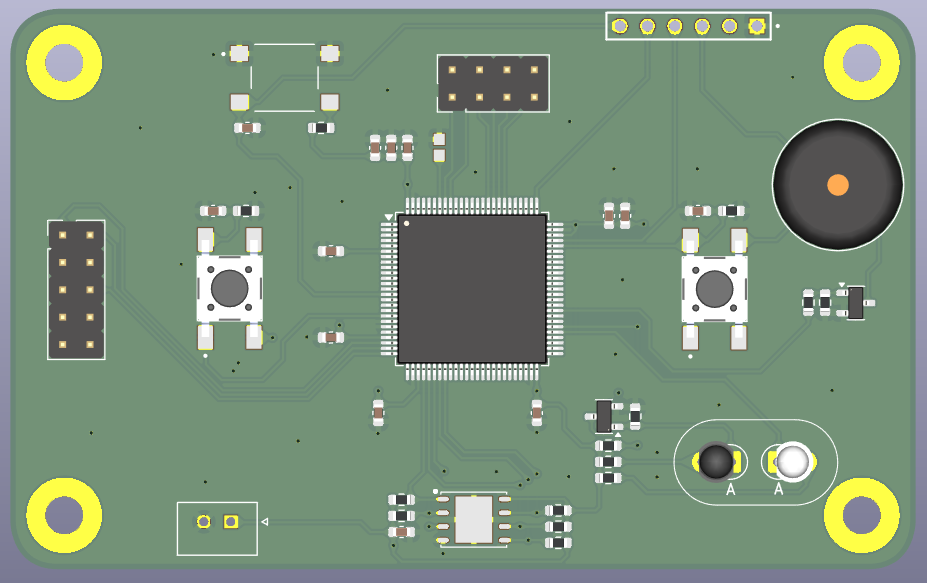
The schematic and PCB layout are in hardware/ as a KiCad project. Open hardware/IR_Programmer.kicad_pro in KiCad to view or edit them, or to generate Gerber and BOM files for manufacturing.
| Beeps | Link | Meaning |
|---|---|---|
| 1 | IR | No reply to 0x7F. The target is not in bootloader mode, the IR link is misaligned, or the baud rate is wrong |
| 2 | IR | Get ID failed |
| 3 | IR | Erase failed |
| 4 | IR | Write failed |
| 5 | SWD | Attach failed (no IDCODE, wrong chip, or the core could not be halted) |
| 6 | SWD | Flash unlock failed |
| 7 | SWD | Erase/program failed |
| 8 | SWD | Verify mismatch |
Connect a USB-UART adapter to J3 (115200 8N1) to see a step-by-step log of every cycle, including the target ID, progress and the reason for any failure.
The image to be programmed is compiled into the programmer as a C array in firmware/Core/Inc/fw_image.h:
static const uint8_t fw_data[] = { 0x00, 0x50, 0x00, 0x20, /* ... */ };
static const uint32_t fw_size = sizeof(fw_data);
The repository ships with a 3-byte placeholder. To use your own firmware:
.bin) that starts at 0x08000000.xxd -i -n fw_data app.bin > fw_array.txtfw_image.h and keep the fw_data / fw_size names.Both the IR and SWD paths use the same image. The image has to fit in the programmer's own flash (128 KB on the STM32L073VB) next to the programmer firmware (about 24 KB).
These settings are at the top of firmware/Core/Src/main.c:
| Macro | Default | Purpose |
|---|---|---|
IR_BAUDRATE | 115200 | IR link speed. Try 57600 or 38400 if the link is marginal. After changing it, power-cycle the target, because the bootloader locks onto the first baud rate it sees |
TARGET_FLASH_BASE | 0x08000000 | Address the image is written to |
SWD_CLK_DELAY | 0 | SWD half-period delay. Increase it to 2–6 on long or noisy cables if you see parity, ACK or verify errors |
firmware/MDK-ARM/IR_PROGRAMMER.uvprojx.firmware/MDK-ARM/IR_PROGRAMMER.bin.fw_image.h you will probably go over that limit. In that case, use a licensed MDK (the free MDK Community or MDK for STM32 licenses also work) or port the project to STM32CubeIDE / GCC.firmware/IR_PROGRAMMER.ioc matches the code and can be regenerated safely. All custom code is kept inside USER CODE BEGIN/END blocks. When you edit generated files, keep your changes inside those blocks, or CubeMX will overwrite them.firmware/
Core/
Inc/fw_image.h firmware image to be programmed (placeholder)
Inc/sys_conf.h software version
Src/main.c IR bootloader client, SWD flow, buttons, buzzer, log
SWD/
inc/swd.h SWD driver API and pin configuration
src/swd.c bit-bang SWD + STM32L0 flash programming
Drivers/ STM32L0 HAL and CMSIS (from ST)
MDK-ARM/ Keil project
IR_PROGRAMMER.ioc STM32CubeMX configuration
hardware/
IR_Programmer.kicad_pro KiCad project
IR_Programmer.kicad_sch schematic
IR_Programmer.kicad_pcb PCB layout
docs/
pcb_3d.png 3D render of the boardswd.c and TARGET_PAGE_SIZE.This project was developed with the help of AI (Claude Code by Anthropic). The AI was used for:
The code is provided as-is (see LICENSE). AI-generated code can contain mistakes that are hard to spot, so review the source and test it on your own hardware before relying on it, especially if you change the target family, the flash layout or the timing settings. Bug reports and pull requests are welcome.
The original code of this project is released under the MIT License.
The bundled ST HAL (BSD-3-Clause) and CMSIS (Apache-2.0) files under firmware/Drivers/ keep their own licenses.
| Qty | Value | Footprint | References |
|---|---|---|---|
| 9 | 10K | Resistor_SMD:R_0603_1608Metric | R1, R2, R3, R5, R6, R8, R10, R13, R15 |
| 8 | 100nF | Capacitor_SMD:C_0603_1608Metric | C3, C6, C7, C9, C10, C11, C13, C15 |
| 4 | C | Capacitor_SMD:C_0603_1608Metric | C1, C2, C4, C5 |
| 4 | MountingHole | MountingHole:MountingHole_3.5mm_Pad | H1, H2, H3, H4 |
| 2 | DS1042-03-1-8-KKR-160-10 | DS1042-03-1-8-KKR-160-10:DS1042-03-1-8-KKR-160-10 | SW1, SW3 |
| 2 | MMBT3904-TP | Package_TO_SOT_SMD:SOT-23-3 | Q2, Q3 |
| 1 | 100R | Resistor_SMD:R_0603_1608Metric | R9 |
| 1 | 10K | RC0603FR-0710KL:RESC1607X60N | R4 |
| 1 | 1K | Resistor_SMD:R_0603_1608Metric | R12 |
| 1 | 1uF | Capacitor_SMD:C_0603_1608Metric | C14 |
| 1 | 22035025 | SmartCapLib:MOLEX_22035025 | J2 |
| 1 | 220R | Resistor_SMD:R_0603_1608Metric | R7 |
| 1 | 4.7K | Resistor_SMD:R_0603_1608Metric | R14 |
| 1 | Buzzer | Buzzer_Beeper:Buzzer_12x9.5RM7.6 | BZ1 |
| 1 | Conn_02x04_Odd_Even | Connector_PinHeader_2.54mm:PinHeader_2x04_P2.54mm_Vertical | J3 |
| 1 | Conn_02x05_Odd_Even | Connector_PinHeader_2.54mm:PinHeader_2x05_P2.54mm_Vertical | J1 |
| 1 | DS1042-07-1-1KRR16008 | DS1042-07-1-1KRR16008:SW_TS24-62-14-BL-200-SMT-TR-67 | SW2 |
| 1 | LED | Diode_THT:D_T-1_P2.54mm_Vertical_AnodeUp | D1 |
| 1 | LTR-4206E | Diode_THT:D_T-1_P2.54mm_Vertical_AnodeUp | Q1 |
| 1 | PROGRAMMING_1X6 | Programming Connection:Programming Connection | P1 |
| 1 | R | Resistor_SMD:R_0603_1608Metric | R11 |
| 1 | STM32L073VBTx | Package_QFP:LQFP-100_14x14mm_P0.5mm | U1 |
| 1 | W25Q128JVPIQ | MotorPilotLib:W25Q128JVPIQ | U2 |
It measures 84 × 52 mm and has 2 copper layers, 1.6 mm thick.
46 parts, built around the W25Q128JVPIQ, MMBT3904-TP and LTR-4206E. The full list of its parts is on this page, with links to each part's symbol and footprint where PCBKit's library has them.
From the ismaillgunes/IR_Programmer repository on GitHub, at the commit this page was made from: the board is hardware/IR_Programmer.kicad_pcb and its schematic hardware/IR_Programmer.kicad_sch. PCBKit opens the board in the browser, with nothing to install.
Its repository states no licence, so its author keeps all rights: ask ismaillgunes before reusing the design.

mirobotech/CHRP400
CHRP4 (Common Hardware Robotics Project 4, rev. 0) KiCad schematic and PCB design files.


Emute-Lab-Instruments/uSEQ
Hardware & firmware of the uSEQ Live Coding CV & Gate Sequencer

lfantoniosi/CoCoTANG
CoCoTANG upgrades the Radio Shack/Tandy Color Computer with a Tang Nano 20K FPGA board and CoCo 3 video and memory features.

jjCSE113NMT/dsp-neutron-spectrometer
A place to keep all our material related to our senior design project.
