
2 layers47 × 39 mm
Qrss clock tx
swharden/AVR-projects
A collection of standalone AVR projects written in C
32 parts184MIT

 iricryst/ps2-mouse-msx
PS/2 IBM PC Mouse to MSX Mouse Converter KiCad project
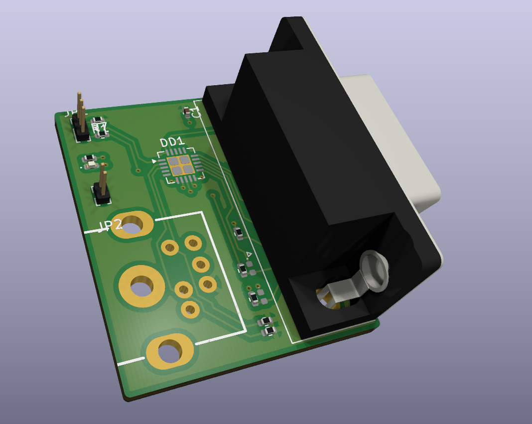
Ps2-mouse msx is an open-source printed circuit board by iricryst, from the iricryst/ps2-mouse-msx repository on GitHub. It is a 2-layer board of 26.4 × 32.1 mm with 17 parts on 25 nets, routed with 142 tracks and 14 vias.
It is built around the ATTINY2313A-SU. Its parts include 8 resistors, 1 capacitor, 1 connector and 1 crystal. It belongs with the retro computing and games boards and the AVR (ATmega, ATtiny) boards of this library.
KiCad schematic project for the 2009 Kami Karilov PS/2-to-MSX mouse converter reference design.
Version 2.0
Warning!!! This is still in concept stage. further testing is required. Not ready for production, please test (electrically) before plug in your MSX / Roland.
BOM not available yet Required parts can be found in the schematic. To keep the pcb clean I removed nearly all markers, deignators and text. Please note the pins on the mini-din connector. I removed pin 2 and 6 to make room for traces and let the Vcc plane intact.
Also, the dsub 9 connector should be the female variant ofcourse. I used the male footprint+3Dmodel in Kicad.
And the ATTiny2313 footprint might be incorrect. As far as I know The center pad should not be split in 4 quadrants. Still needs reviewing.
This manual is adapted from the original project page by Kamil Karimov (caro): https://caro.su/msx/mous4msx.htm
The controller connects to either MSX joystick port and allows an IBM PS/2 mouse to be used as an MSX mouse or as an MSX joystick. The controller is based on an Atmel ATTiny2313 running from its internal 8 MHz oscillator.
WORK (contacts 2-3 closed).If the LED flashes approximately once per second, the mouse was not detected. Check the mouse, its PS/2 compatibility, the PS/2-to-USB adapter if one is being used, and the controller wiring.
The controller can be programmed directly from the MSX joystick port. Set the
switch to PROG (contacts 1-2 closed) before starting the programmer. The
ATTiny2313 connections are:
| ATTiny2313 | Function | MSX joystick pin/signal |
|---|---|---|
| 1 | RESET | 8 / STROBE |
| 17 | MOSI | 6 / TrgA |
| 18 | MISO | 1 / Up |
| 19 | SCK | 7 / TrgB |
| 20 | VDD | 5 / +5 V |
| 10 | GND | 9 / GND |
Confirm the pinout and power wiring before applying power. The original design is experimental and should be electrically tested before connecting it to an MSX or Roland computer.
The software folder contains the original downloads and extracted files:
software/msx_ms21/msx_ms21.hex - firmware version 2.1.software/prg2313t/PRG2313T.COM - MSX programmer version 0.4.software/prg2313t/prg2313t.src/ - programmer source and build files.On an MSX, copy PRG2313T.COM and the desired Intel-HEX file to an accessible
drive, set the controller to PROG, and run:
A>PRG2313T MSX_MS21.HEXThe programmer checks for an ATTiny2313, reads its signature, fuse settings and
current firmware, then updates the fuses for the internal 8 MHz oscillator if
needed. If the firmware differs, it writes and verifies the new image and
reports Ok or Error. Running the command without a HEX filename only
reports the detected controller and its current state.
After programming, power off, return the switch to WORK, and reconnect the
mouse. The included programmer documentation describes the original MSX
environment and command behaviour in more detail.
The files in software/ were downloaded from the original project page on
2026-09-10. They are retained here for use with this hardware project; the
original author and any notices included with the downloaded files remain the
authoritative source for their licensing and redistribution terms.
| Qty | Value | Footprint | References |
|---|---|---|---|
| 4 | 220 | Resistor_SMD:R_0402_1005Metric | R4, R5, R6, R7 |
| 2 | 1N4148 | Diode_SMD:D_0402_1005Metric | VD2, VD3 |
| 2 | 4.7K | Resistor_SMD:R_0402_1005Metric | R2, R3 |
| 1 | 0.1uF | Capacitor_SMD:C_0402_1005Metric | C1 |
| 1 | 1-2 PROG / 2-3 WORK | Connector_PinHeader_1.00mm:PinHeader_1x03_P1.00mm_Vertical | JP1 |
| 1 | 10K | Resistor_SMD:R_0402_1005Metric | R1 |
| 1 | 2K | Resistor_SMD:R_0402_1005Metric | R8 |
| 1 | ATtiny2313 | Package_DFN_QFN:MLF-20-1EP_4x4mm_P0.5mm_EP2.6x2.6mm | DD1 |
| 1 | DE9_Socket | Connector_Dsub:DSUB-9_Pins_Horizontal_P2.77x2.84mm_EdgePinOffset4.94mm_Housed_MountingHolesOffset4.94mm | J1 |
| 1 | MOUSE | LED_SMD:LED_0402_1005Metric | VD1 |
| 1 | MiniDIN6 | ps2usb:DIN8 | X1 |
| 1 | RATIO | Connector_PinHeader_1.00mm:PinHeader_1x02_P1.00mm_Vertical | JP2 |
swharden/AVR-projects
A collection of standalone AVR projects written in C


bga/avr-hid-usb-init-tester
Avr attiny2313 soft usb hid "keyboard" for testing bios usb initialization. Device is blinking if bios assign usb endpoint address and continue sending USB SOF (ie bios in alive).


lyase/hello-bulb
making the simplest usb device using atmel2313 the board design is available in kicad format .code is c, licence GPL V3

It measures 26.4 × 32.1 mm and has 2 copper layers, 1.6 mm thick.
17 parts, built around the ATTINY2313A-SU. The full list of its parts is on this page, with links to each part's symbol and footprint where PCBKit's library has them.
From the iricryst/ps2-mouse-msx repository on GitHub, at the commit this page was made from: the board is ps2_mouse_msx.kicad_pcb and its schematic ps2_mouse_msx.kicad_sch. PCBKit opens the board in the browser, with nothing to install.
Its repository states no licence, so its author keeps all rights: ask iricryst before reusing the design.