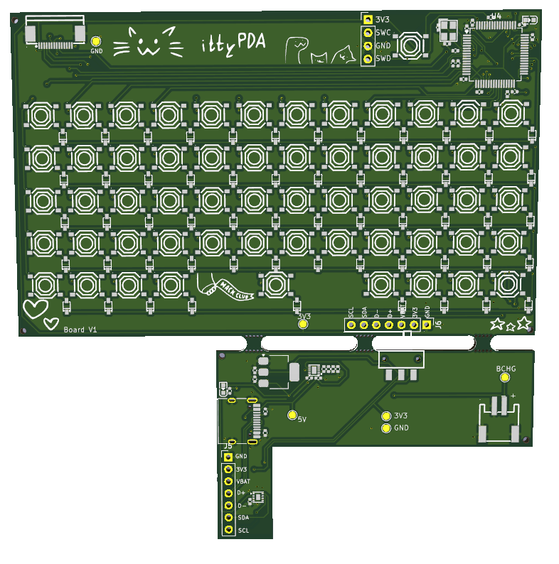
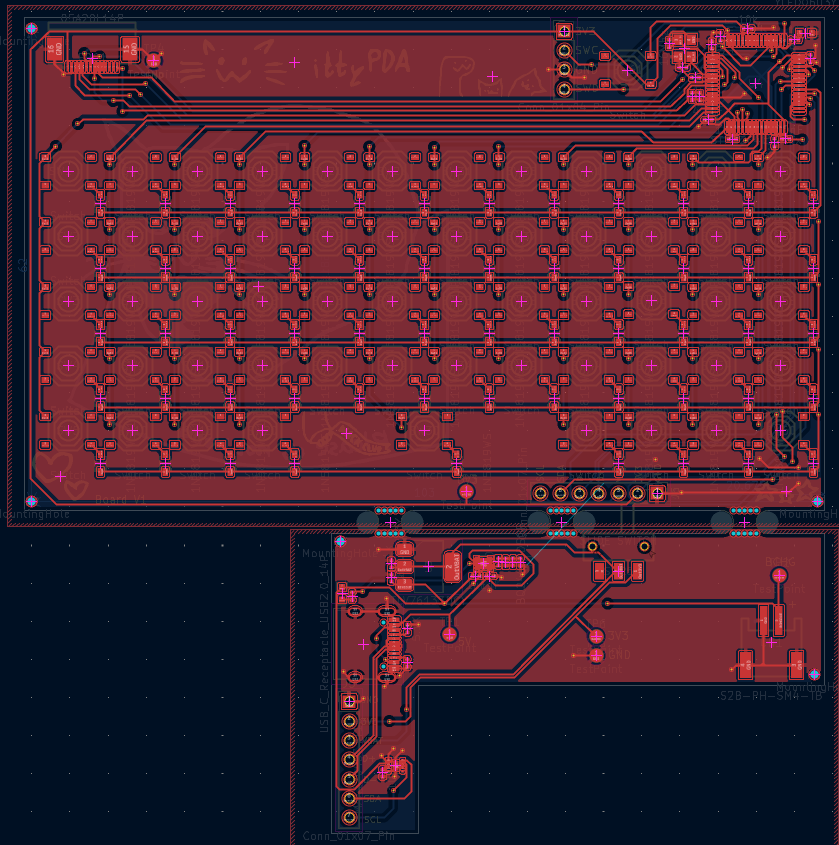
Ittypda is an open-source printed circuit board by ingobeans, from the ingobeans/ittypda repository on GitHub. It is a 2-layer board of 105 × 107.2 mm with 175 parts on 256 nets, routed with 946 tracks and 147 vias.
It is built around the BQ24040DSQR, MAX17048G+T10 and TLV76133DCY, with the TS-1187A-B-A-B, 1N5819WS and YLED0603Y among its other parts. Its parts include 59 diodes, 59 switches, 17 capacitors, 9 resistors and 5 connectors. It belongs with the STM32 boards of this library.
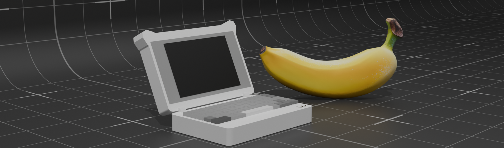
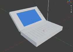
ittyPDA is an itty-bitty PDA/cyberdeck thingy. its smaller than a nintendo ds but has a real keyboard and a full color IPS LCD display, powered by an STM32 microcontroller. its my first ever hardware project and first time designing a pcb !!
it's mainly intended for note-taking/writing, playing silly little videogames, and just being a very hackable little computer.
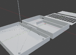
this repo contains both the hardware designs, under the ittypda/ subdirectory, as well as the operating system under ittyOS/. 3D case files are under case/.
on-board charging circuitry powered by a BQ24040DSQR
also battery level sensing
download symbols/footprints
to open the kicad project, youll need to download some footprints. my parts are sourced from JLCPCB's parts / LCSC, and you can use easyeda2kicad to download LCSC parts to kicad.
which will download footprints/symbols/3d models for the switches, diodes, etc.
project status (important !!)
project is in a very early WIP state currently! the PCB is the only truly finished part so far.
the case is just a minimum-viable-product for now, and the firmware mostly acts as a proof-of-concept regarding graphics streaming and input handling from the keyboard matrix.
thus the project is mostly about the creation of the PCB, with the case and firmware mostly just acting as beta features used to test the PCB itself.
these features will be developed in the coming months though, and when i have guaranteed that the core PCB does work! this is a project i intend to gradually work on for a long time !
schematic / PCB
the schematic and PCB are designed in KiCad, files for which are found in ittypda/.
the PCB is split in two seperate parts. this is done to achieve a budget 4-layer board, and to get around the fact that JLCPCB's economy PCBA service cant assemble parts on the bottomside of the board.
the mainboard houses the microcontroller, the keypad, and display connector.
the secondary board houses the usb-c port, battery charging ic, voltage regulator, etc.
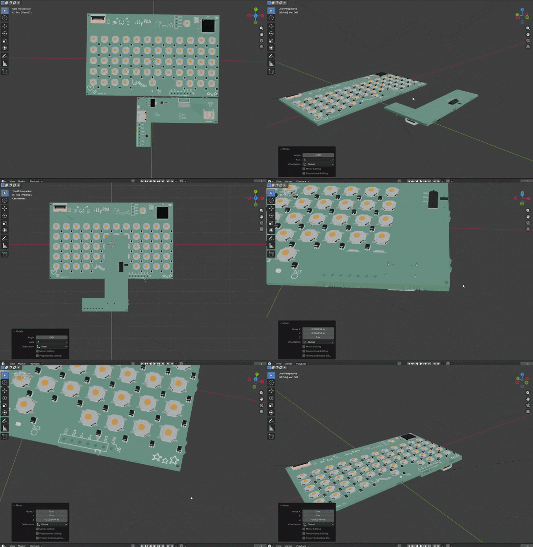
the two boards mount together like a PCB-sandwich and connect through 7 soldered pads.
showcase how the two boards are mounted:
<img src=readme/schematic.png width=400>
firmware - ittyOS
ittyOS is currently in an early proof of concept state, but will have many different apps later on.
<img src=readme/home.png width=200>
implemented:
display drivers
reading from microSD card
streaming image data from microSD to screen
input from keyboard
program switching
basic home screen
basic notes app
todo:
improve text input
usb file transfer
more apps!
wordle
journal
different themes?
compile ittyOS
the ../firmware folder contains the low level hardware setup for different boards that can run ittyOS, while ittyOS/ contains the shared code and the actual system, which is then linked to from the firmware.
you'll need to generate the firmware code from the STM32 project file, since the low-level drivers for these boards are very large and therefore gitignored. you'll need STM32CubeMX. then just open the project file for the firmware you want to build, and hit generate code.
you'll also have to tell your LSP which CMakeLists you're using.
then, to build, navigate to the firmware you want to build's directory.
cmake --preset Debug (you only have to run this once)
cmake --build --preset Debug
STM32_Programmer_CLI -c port=swd -w build/Debug/<DEVBOARD OR ITTYPDA HERE>.elf -v -rst
case
the case files are located under case/.
the case is designed in,.. blender. its mostly a MVP for a case, and when i get the phyiscal PCB, this and the firmware will be the major focus for the project moving forwards.
most parts are designed to friction-fit, though i wont know how well this works in practice, but will find out soon !
It measures 105 × 107.2 mm and has 2 copper layers, 1.6 mm thick.
What parts does the Ittypda use?
175 parts, built around the BQ24040DSQR, MAX17048G+T10, TLV76133DCY and TS-1187A-B-A-B. The full list of its parts is on this page, with links to each part's symbol and footprint where PCBKit's library has them.
Where can I download the Ittypda KiCad files?
From the ingobeans/ittypda repository on GitHub, at the commit this page was made from: the board is ittypda/ittypda.kicad_pcb and its schematic ittypda/ittypda.kicad_sch. PCBKit opens the board in the browser, with nothing to install.
Can I use the Ittypda design in my own project?
Its repository states no licence, so its author keeps all rights: ask ingobeans before reusing the design.
A modern remake of the Bare Conductive Touch Board: 12 capacitive touch electrodes, MP3/WAV/MIDI audio, and now WiFi, Bluetooth LE, USB-C, a proper LiPo power path, a fuel gauge, line-in, MIDI out, Qwiic and an RGB LED.
Owl-shaped Spotify remote for your desk and pocket: ESP32-S3 firmware, LVGL UI, KiCad PCB, 3D-printed enclosure, and owl v0 on the Waveshare AMOLED kit