simpl-slidrr
A cost-effective(ish), Raspberry Pi Pico based controller that aims to perform well while being easy to assemble
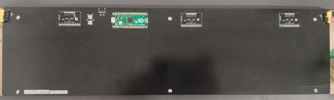
About the project
I was looking to build a controller from the projects that were already available but none of them were as accessible due to not being able to 3D print anything among other things.
This project aims to make these types controllers more accessible to more people to either improve on or use as-is.
If you want to know more about the firmware itself check out the repo!
I'm sorry it's heavily vibecoded I don't know C
[!Warning]
I am just a hobbyist maker that has no acedemic qualifications so if there's something
that looks off to you please bear this warning in mind.
Also the case design has changed quite a bit but shouldn't affect the final product but any photos of the controller that are used in this README are going to be different.
Build guide
As of writing this, this is a very rough guide for now.
PCB Parts list
This is only for the main PCB, For the air towers refer to whowechina's chu_pico project for the air tower assembly.
| Item | Description | Quantity |
|---|
| Raspberry Pi Pico | The main MCU for the controller | 1 |
| MPR121 | Capacitive touch boards | 3 |
| USB C Breakout board | Specifically one like this, Realistically any 4pin, 2.54mm pitch breakout board would probably work but make sure the pinout is the same as in the picture | 1 |
| XKB Connection TS-1187A-B-A-B Button | Push buttons for the TEST and SERVICE Buttons | 2 |
| Horizontal / 90 Degree pin headers | For the Air Wires, 6 pins per side | 1 |
| Dupont style jumpers | For connecting the Air PCBs to the main PCB | 1 |
Case parts list
| Item | Description | Quantity |
|---|
| Base Parts | Main case files, 3mm thickness of any material but acrylic is preferred | 1 |
| (Optional) Extended Base Piece | This is an extended base which is longer so that the airs are further and lessen the chances of your hands hitting them during play. The base parts are meant to be economical, If you choose this route you can omit/remove this part of the Base file | 1 |
| Angle bracket | Currently the design only supports 20mm x 20mm x 16mm brackets with these measurements, You'd need to modify the CAD on your own for other bracket sizes and possibly also the following screws needed | 4 |
| Chicago Screw M5, 7mm long | For mounting the air tower pieces to the base of the case | 4 |
| Chicago Screw M5, 4mm long | For mounting the air tower pieces to the base pieces themselves | 4 |
| Chicago Screw M3, 6mm long | For mounting the acrylic stack to the PCB on the bottom half | 3 |
| Chicago Screw M3, 10mm long | For mounting the acrylic stack to the PCB on the top half with the guard | 3 |
| Chicago Screw M3, 5mm long | For mounting the air PCBs to the air tower acrylics | 6 |
PCB Assembly
Pre-requisites
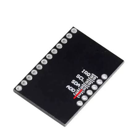
Cutting the ADDR pads on the MPR121s.
As far as I know all the MPR121s ADDR pins are connected to GND. You will need to use an exacto knife or similar to cut the pad on the bottom of the PCB as shown here. Verify the cut with a Multimeter.
Assembly
- Soldering the Pi Pico
Soldering the Pi Pico is pretty straight forward aside from the Data test pads on the bottom side of the pico.
Depending on your experience in soldering this might be hard, I recommend using a pointed cone tip for this and make sure no air bubbles reside.
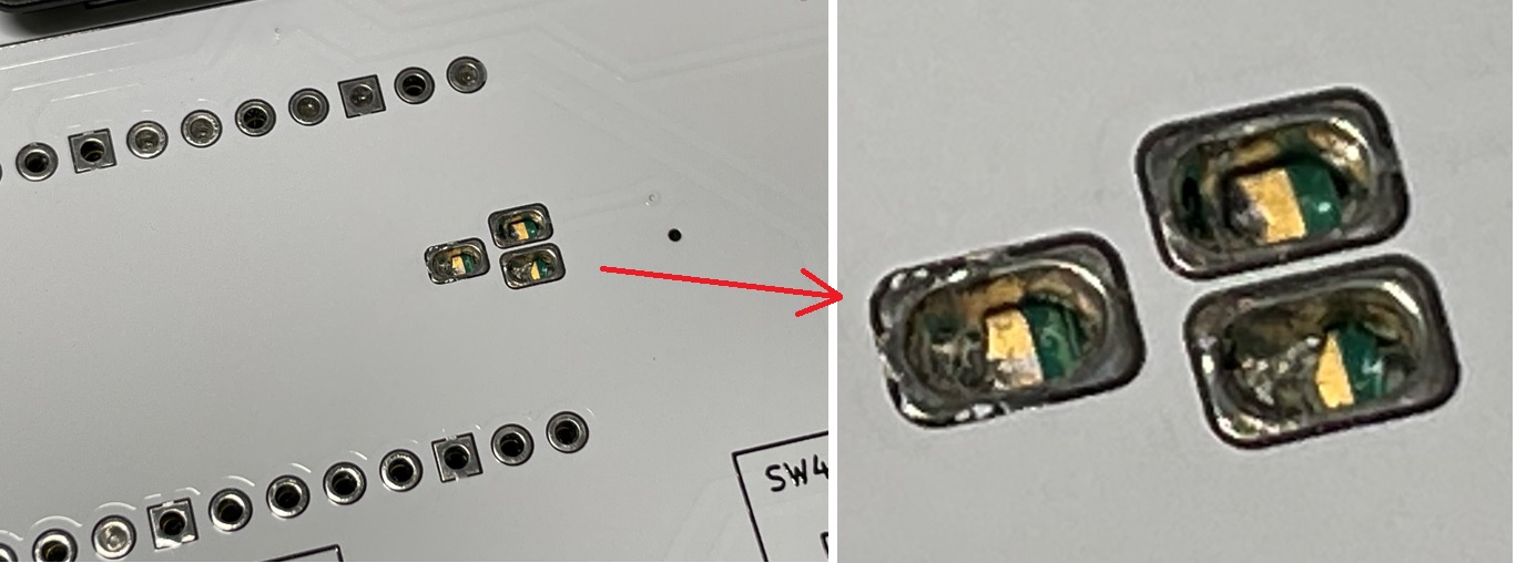
Credits to whowechina for the image
-
Soldering the MPR121s
I have incorporated a somewhat unique way to solder these due to where these modules sit on the board.
Standard Pin headers work but it runs the risk of your finger getting scraped by the sharp ends during play.
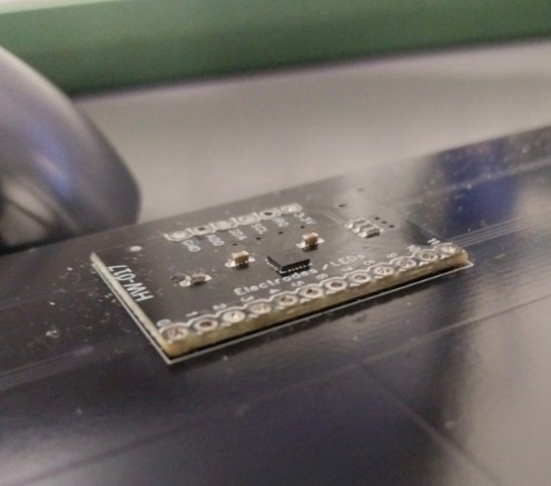
You'll need a sharp pointed soldering tip to mount these onto the PCB.
As for demonstration there is a video on how I soldered these boards.
Video linked over here
Notice how the solder sinks down, also check on the side if there's bridges between other pads but mainly to verify the solder has reached the PCB's pads below
You can also mount the USB-C breakout board the same way
Other than that soldering everything else should be standard.
Case assembly
Once you get the PCB assembled now we can move on to the case assembly.
The case should be assembled like this:
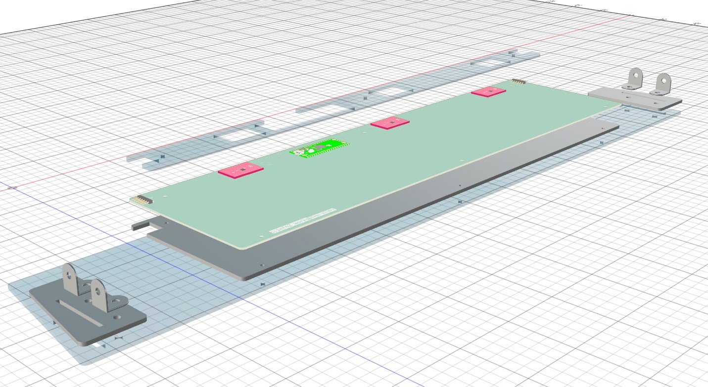
These are the chicago screw locations for the base
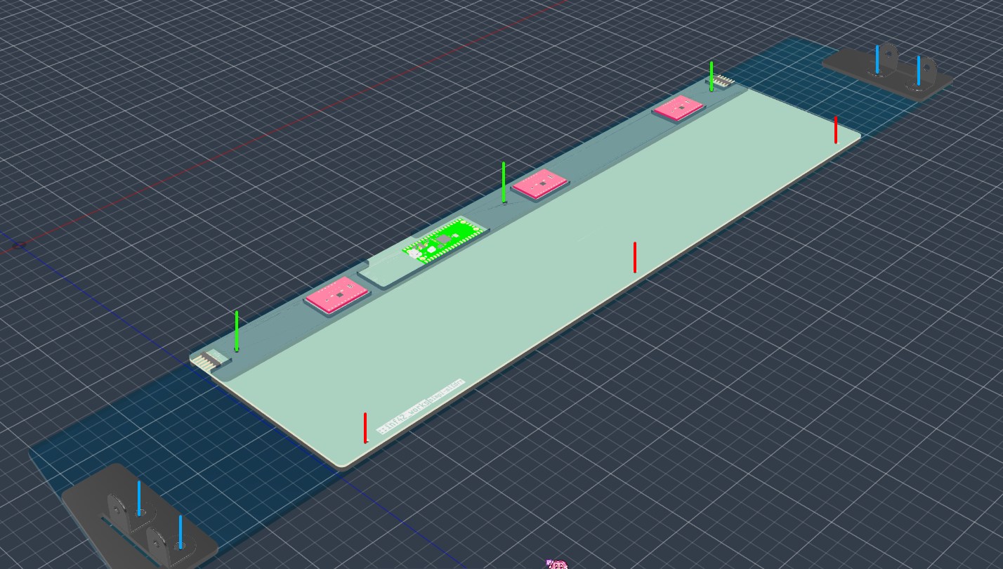
| Color | Screw Type |
|---|
| Green | M3*10 |
| Red | M3*6 |
| Blue | M5*7 |
And on the Air towers:
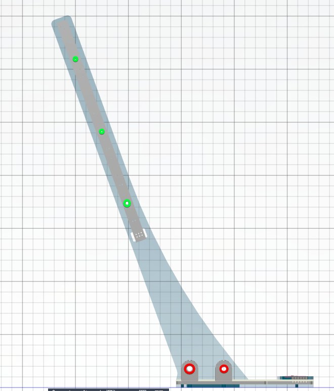
| Color | Screw Type |
|---|
| Green | M3*5 ** |
| Red | M5*4 |
**Small side note: You might need washers if the M3 screws are loose
Wires Should be routed through the hole of the air tower piece so that your hands don't get caught on them during play
Regarding Air PCB Placement
If you wire the Air PCBs according whowechina's chu_pico guide, you might find that the Airs are reversed.
To fix that, switch J2 to the left side and J1 to the right side.
Flash the firmware from whowechina's chu_pico or my fork, simpl-slidrr-firmware
After all that you should (hopefully) have a functioning controller!
Credits and attributions
I want to give my thanks to the Cons&Stuff Discord with help for designing the PCB and whowechina for the chu_pico project! Without it, this project would have never existed.
PCB:
PCB/libraries/TouchPad.pretty is by skogaby/skogasliderPCB/libraries/RP_Silicon_KiCad is by HeadBoffinPCB/libraries/chu_pico_lib.pretty and PCB/libraries/_3dmodels is by whowechina
Firmware
Most of the firmware is built on top of whowechina's chu pico firmware.


