2 layers97.3 × 120.4 mm

 todbot/synthiota25
Pico/Pico2-based board for playing with synthesizers in CircuitPython
Synthiota1 is an open-source printed circuit board by todbot, from the todbot/synthiota repository on GitHub, published under the GPL-3.0 licence. It is a 2-layer board of 177.8 × 114.3 mm with 112 parts on 151 nets, routed with 837 tracks and 103 vias.
It is built around the MPR121QR2, 74HC4051 and H11L1, with the SK6812MINI-E among its other parts. Its parts include 33 capacitors, 28 diodes, 8 resistors, 4 ICs and 2 connectors. It belongs with the audio and music boards and the RP2040 boards of this library.


Pico/Pico2-based board for playing with synthesizers in CircuitPython.
https://github.com/user-attachments/assets/3d1baa3f-af72-41ba-9afe-a45eea070c66
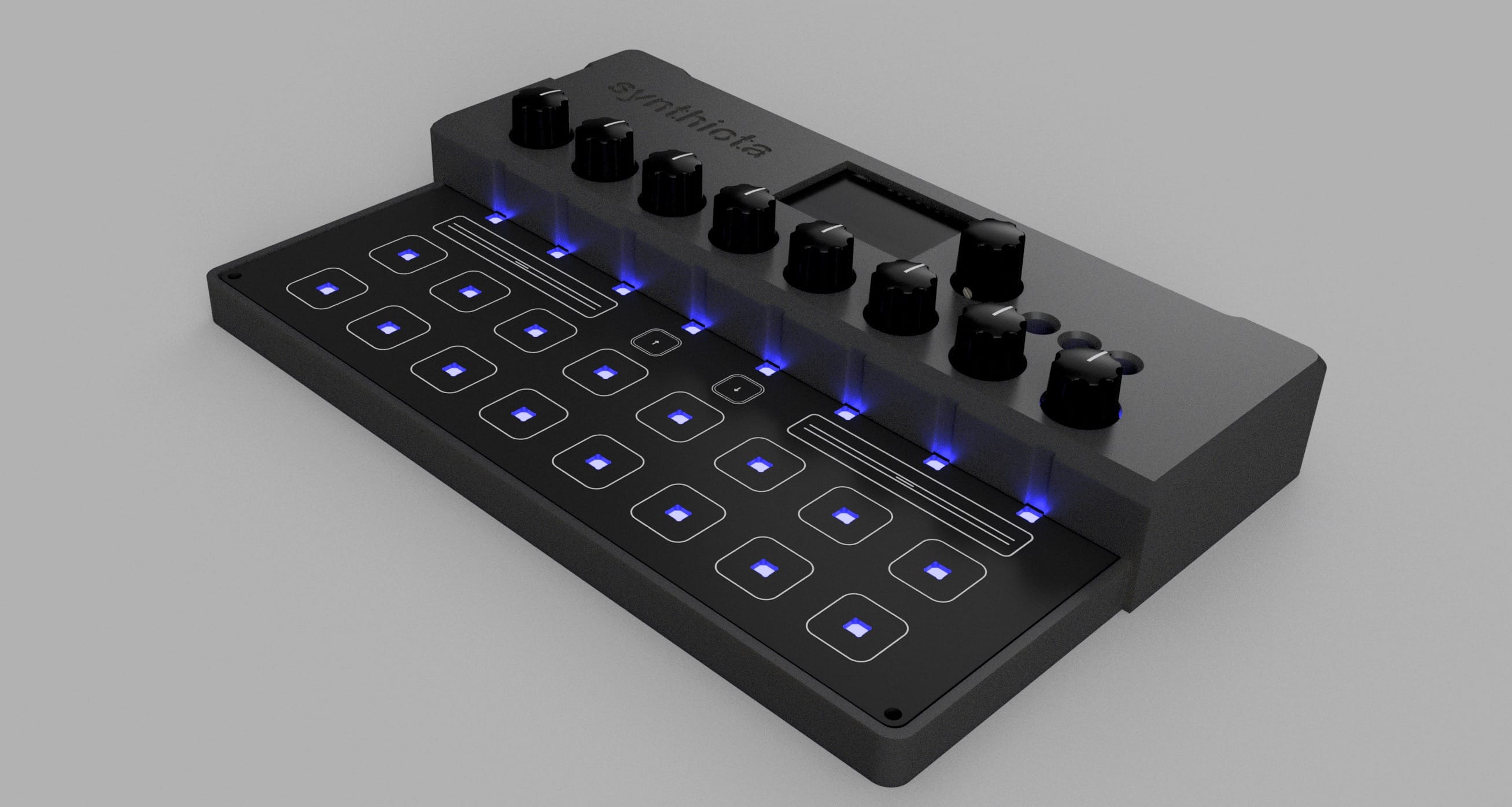
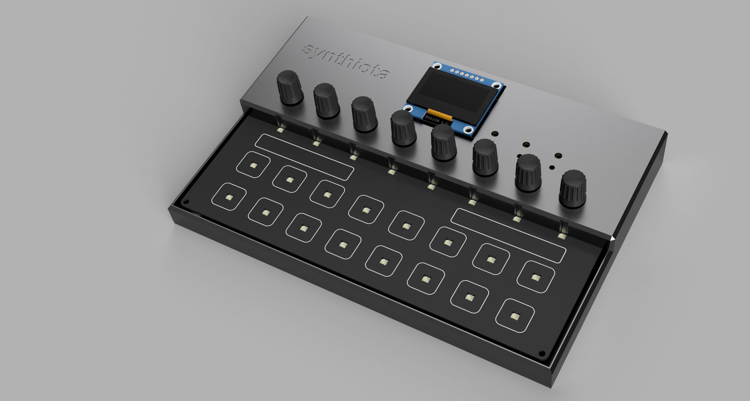
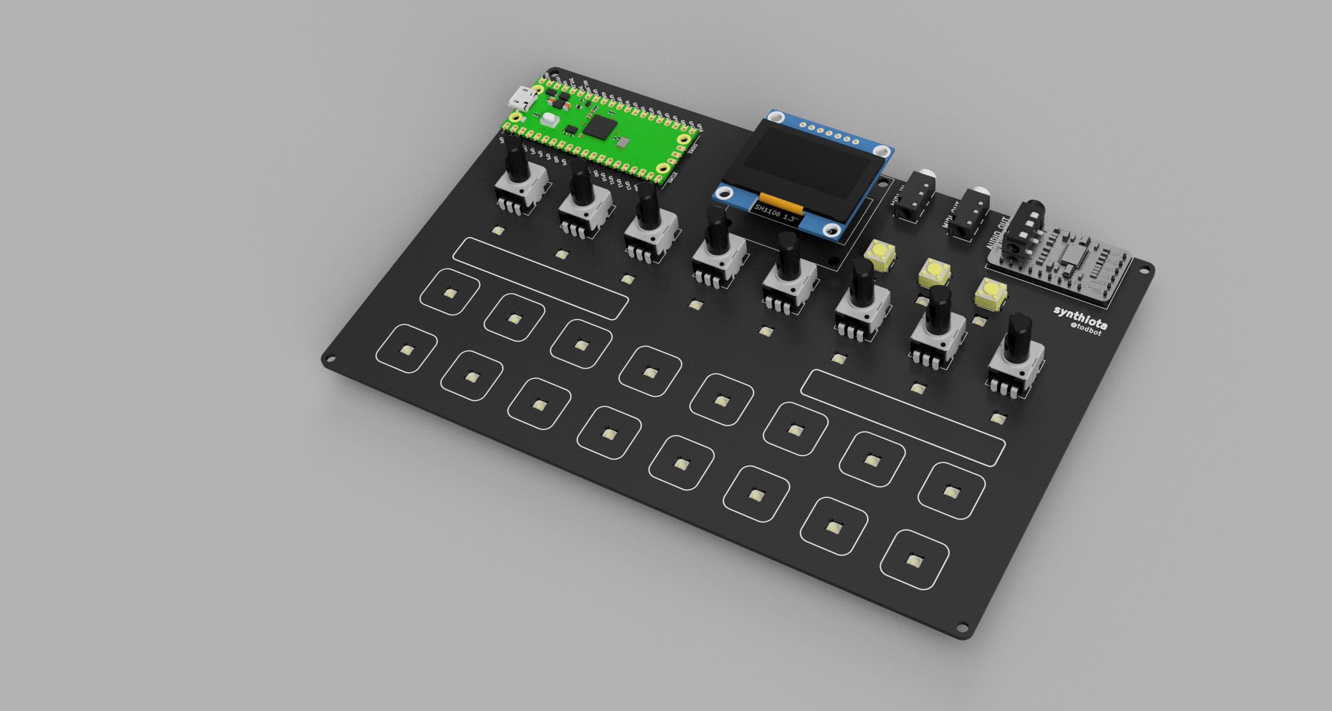
Each app's folder has a README with its controls. To install, find the corresponding UF2 in the Releases section and copy the UF2 to the board in BOOT mode. Or look in the app's directory for how to install it.
CircuitPython, in circuitpython/:
polysynth -- two-oscillator
subtractive polysynth. The pads are a chromatic keyboard and the pots
edit 16 params over 2 pages.wavesynth -- wavetable polysynth. The
pads are a scale keyboard, with chords on the top row, and the pots
edit 24 params over 3 pages.swarmsynth -- Swarmatron-style drone:
eight oscillators on one pitch, fanned apart by the right slider.dronesynth -- eight drone oscillators,
each tuned by its own knob, each with its own LFO.dronesynth_wt -- dronesynth with
each oscillator at its own place in a shared wavetable.tbish2 -- TB-303-style acid bassline with
a 16-step sequencer you can edit on the board.tbish -- the original TB-303-style synth,
a technology demo with no pattern editing or MIDI in.hwtest -- hardware bring-up tests and the
reference pin setup.Arduino, in arduino/:
wavesynth -- a Mozzi port of the
CircuitPython wavesynth, in progress. It serves the CIRCUITPY drive
over USB for wavetables and patches.hwtest -- a board test, plus simple mono MIDI
synths using M16 and Mozzi.See Getting to BOOT mode via commandline for another way to install these apps.
The PCBAs come with all SMD parts assembled. The components you will need to supply:
For the knobs, you can buy knobs off Amazon or you can 3d print them. Some 3D printable knobs I like are these 6mm Vintage Synth Knob.
Before soldering down the PCM5102 DAC, solder bridge the jumpers to be 1L/2L/3H/4L, as in this picture:
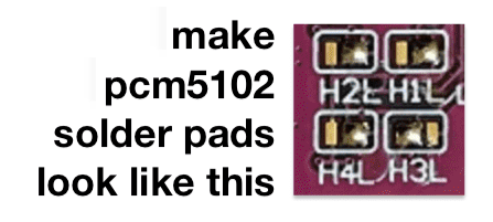
The PCM5102 DAC should have standard header pins soldered to it, on the 6-pin header row. For extra stability, you can also solder one of the G pins behind the audio jack.
More inforomation about the PCM5102 can be found in this blog post.
You will also need some headers and header sockets to attach the modules to the PCB. If using the enclosure, the top part expects the header arrangement to be:
When soldering down the jacks and sockets, holding them in place with masking tape or blutack makes things easier. For the Pico header sockets, sticking them into a Pico and hold the Pico onto the board with masking tape or blutack can be helpful.
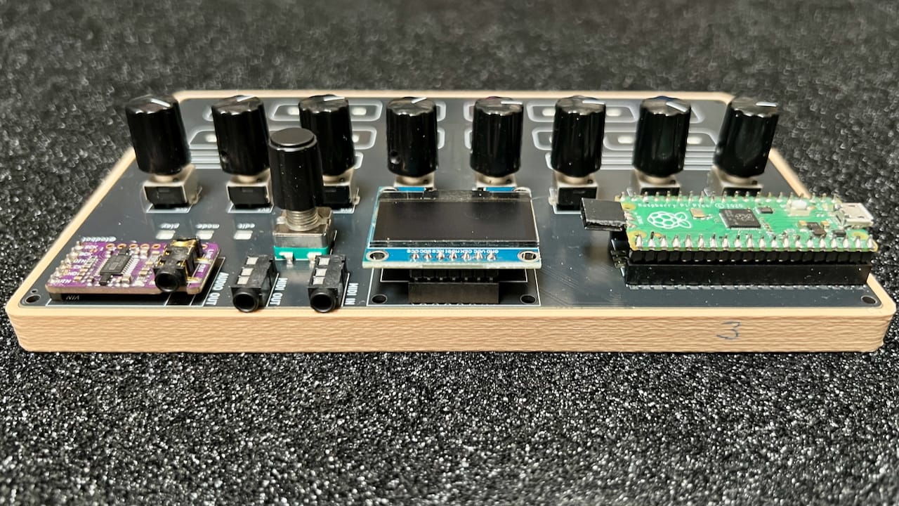
After soldering everything, the result will look like:
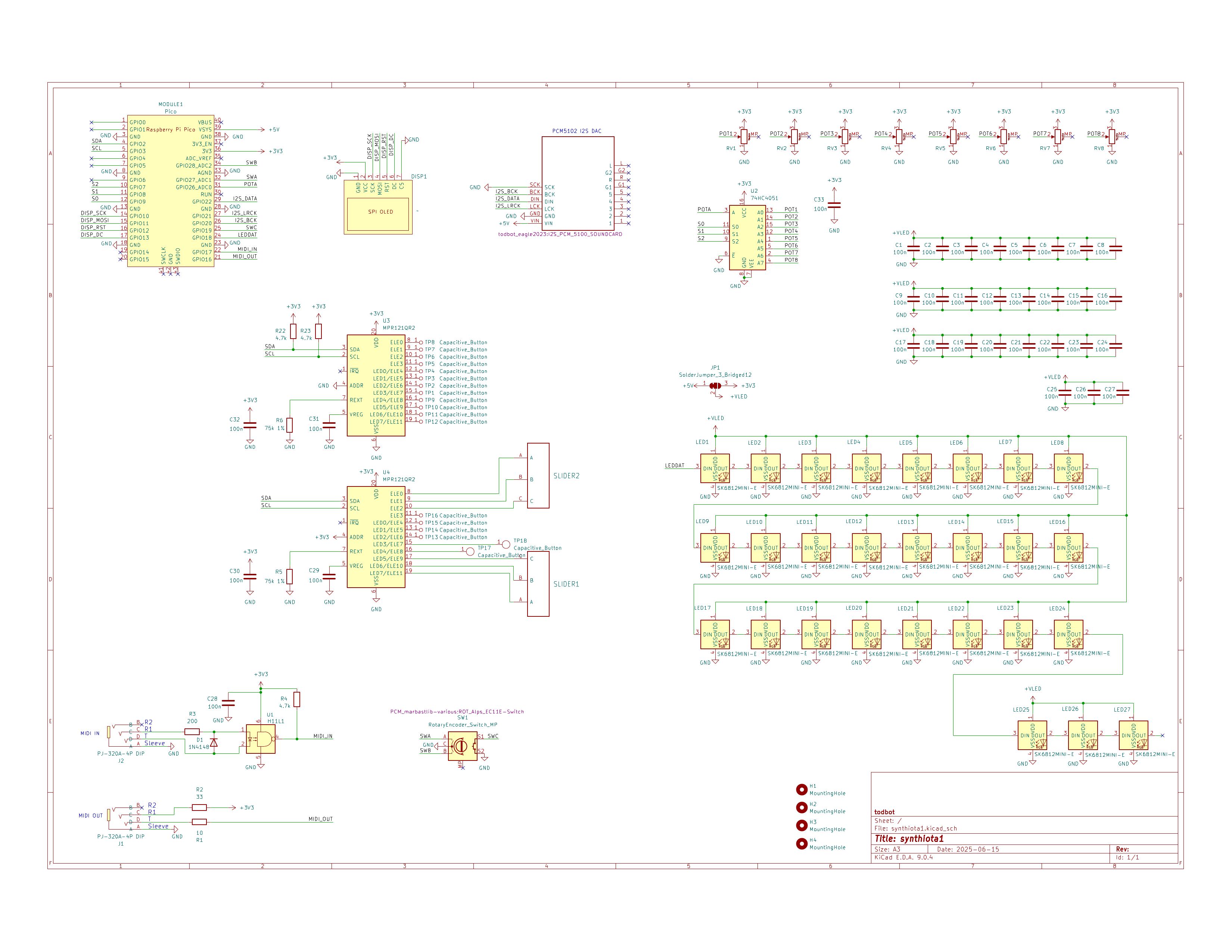
CircuitPython naming. See hwtest/synth_setup_synthiota.py for how they're used.
Encoder
board.GP28 - encoder B pinboard.GP27 - encoder A pinADC input for pots
board.GP26 - ADC input for pot knobsI2S DAC
board.GP22 - I2S DAT pin to PCM5102 DACboard.GP21 - I2S LCK pin to PCM5102 DACboard.GP20 - I2S BCK pin to PCM5102 DACEncoder switch
board.GP19 - encoder SW pinNeoPixel LEDs
board.GP18 - NeoPixel LEDs pinUART MIDI In/Out
board.GP17 - UART RX pin to MIDI inputboard.GP16 - UART TX pin to MIDI outputSPI for display
board.GP13 - SPI DC for SH1106 displayboard.GP12 - SPI RES for SH1106 displayboard.GP11 - SPI MOSI for SH1106 displayboard.GP10 - SPI SCK for SH1106 displayPot mux select
board.GP9 - SEL A pin to 4051 mux for pot knobsboard.GP8 - SEL B pin to 4051 mux for pot knobsboard.GP7 - SEL C pin to 4051 mux for pot knobsI2C for MPR121 touch sensors
board.GP3 - I2C SCL to MPR121 touch sensorsboard.GP2 - I2C SDA to MPR121 touch sensorsFree pins: GP0,GP1, GP4,GP5,GP6, GP14,GP15. Feel free to use for other purposes.
If you don't want to hold the BOOT button down while powering on, you can usually get the synthiota board into BOOT mode via the commandline with:
PORT=/dev/cu.usbmodem21301   # the COM port of the Pico
python3 -c "import serial;serial.Serial('$PORT',1200).close()"
If you don't want to use Python, one of these should work:
stty -f $PORT 1200  # MacOS
stty -F $PORT 1200  # Linux
To install a UF2 once in BOOT mode, you can do (this flashes and starts the program):
picotool load -x file.uf2Or picotool reboot to reset board.
(if you need, pip3 install pyserial and brew install picotool)
(note most product links are Amazon affiliate links)
https://github.com/user-attachments/assets/1fe45b23-2a2a-41f4-9afe-203840c703e8
| Qty | Value | Footprint | References |
|---|---|---|---|
| 33 | 100n | Capacitor_SMD:C_0603_1608Metric | C1, C2, C10, C11, C12, C13, C14, C15, C16, C17, C18, C19, C20, C21, C22, C23 +17 |
| 27 | SK6812MINI-E | PCM_marbastlib-various:LED_6028R | LED1, LED2, LED10, LED11, LED12, LED13, LED14, LED15, LED16, LED17, LED18, LED19, LED20, LED21, LED22, LED23 +11 |
| 16 | Capacitive_Button | todbot_eagle2023:TOUCHPAD_KEY_0.5IN_LEDHOLE | TP1, TP2, TP3, TP4, TP5, TP6, TP7, TP8, TP9, TP10, TP11, TP12, TP13, TP14, TP15, TP16 |
| 8 | R_Potentiometer_MountingPin | todbot_stuff:Potentiometer_Alps_RK09K_Single_Vertical | RV1, RV2, RV3, RV4, RV5, RV6, RV7, RV8 |
| 4 | MountingHole | MountingHole:MountingHole_2.7mm_M2.5 | H1, H2, H3, H4 |
| 3 | 4.7k | Resistor_SMD:R_0603_1608Metric | R4, R22, R23 |
| 2 | 75k 1% | Resistor_SMD:R_0603_1608Metric | R5, R6 |
| 2 | Capacitive_Button | todbot_stuff:Pad-CapTouch-8mm-roundrect | TP17, TP18 |
| 2 | MPR121QR2 | Package_DFN_QFN:UQFN-20_3x3mm_P0.4mm | U3, U4 |
| 2 | PJ-320A-4P DIP | easyeda2kicad:AUDIO-TH_PJ-320A-4P-DIP | J1, J2 |
| 2 | ~ | todbot_stuff:TouchSlider3_50x8mm_ti | SLIDER1, SLIDER2 |
| 1 | 10 | Resistor_SMD:R_0603_1608Metric | R1 |
| 1 | 1N4148 | Diode_SMD:D_SOD-123 | D1 |
| 1 | 200 | Resistor_SMD:R_0603_1608Metric | R3 |
| 1 | 33 | Resistor_SMD:R_0603_1608Metric | R2 |
| 1 | 74HC4051 | easyeda2kicad:SOIC-16_L9.9-W3.9-P1.27-LS6.0-BL | U2 |
| 1 | H11L1 | easyeda2kicad:SMD-6_L7.3-W6.5-P2.54-LS10.2-BL | U1 |
| 1 | Pico | todbot_RPI_Pico:RPi_Pico_SMD_TH | MODULE1 |
| 1 | RotaryEncoder_Switch_MP | PCM_marbastlib-various:ROT_Alps_EC11E-Switch | SW1 |
| 1 | SolderJumper_3_Bridged12 | Jumper:SolderJumper-3_P1.3mm_Bridged12_RoundedPad1.0x1.5mm | JP1 |
| 1 | ~ | todbot_eagle2023:I2S_PCM_5100_SOUNDCARD | MODULE2 |
| 1 | ~ | todbot_eagle2023:DISPLAY-OLED-128X64-1.3IN | DISP1 |
It measures 177.8 × 114.3 mm and has 2 copper layers, 1.6 mm thick.
112 parts, built around the MPR121QR2, 74HC4051, H11L1 and SK6812MINI-E. The full list of its parts is on this page, with links to each part's symbol and footprint where PCBKit's library has them.
From the todbot/synthiota repository on GitHub, at the commit this page was made from: the board is schematics/synthiota1/synthiota1.kicad_pcb and its schematic schematics/synthiota1/synthiota1.kicad_sch. PCBKit opens the board in the browser, with nothing to install.
Its repository publishes it under the GPL-3.0 licence: you may reuse it on that licence's terms (keep the author's notice, and for a copyleft licence share your changes alike).


sporkus/le_capybara_keyboard
Capactive sensing (EC) pcb for Le Chiffre keyboard

ginjake/ec_helix_build
商用利用したい場合は twitter @sirojake にご相談ください please contact me for commercial use. ## developer ginjake

byungyoonc/TrueStrike42
TrueStrike42 is a columnar staggered unibody split keyboard designed to maximize performance and minimize finger fatigue.

byungyoonc/TrueStrike56
TrueStrike56 is a columnar staggered unibody split hall effect keyboard with popular 4x6_4 layout.

calvin-mcd/the-nicholas-van
EC (topre) PCB for trashman's vanagon