2 layers27 × 25 mm
LightSound
sean618/MakerTiles
Modular STM32 electronic-tile system: hardware, firmware, the MicroBus + Field Protocol stack, and a Python daemon.
23 partsMIT

 Incomprehensible/Mad_Bot1
Exploratory project in Embedded and Multi-Agent Robotics
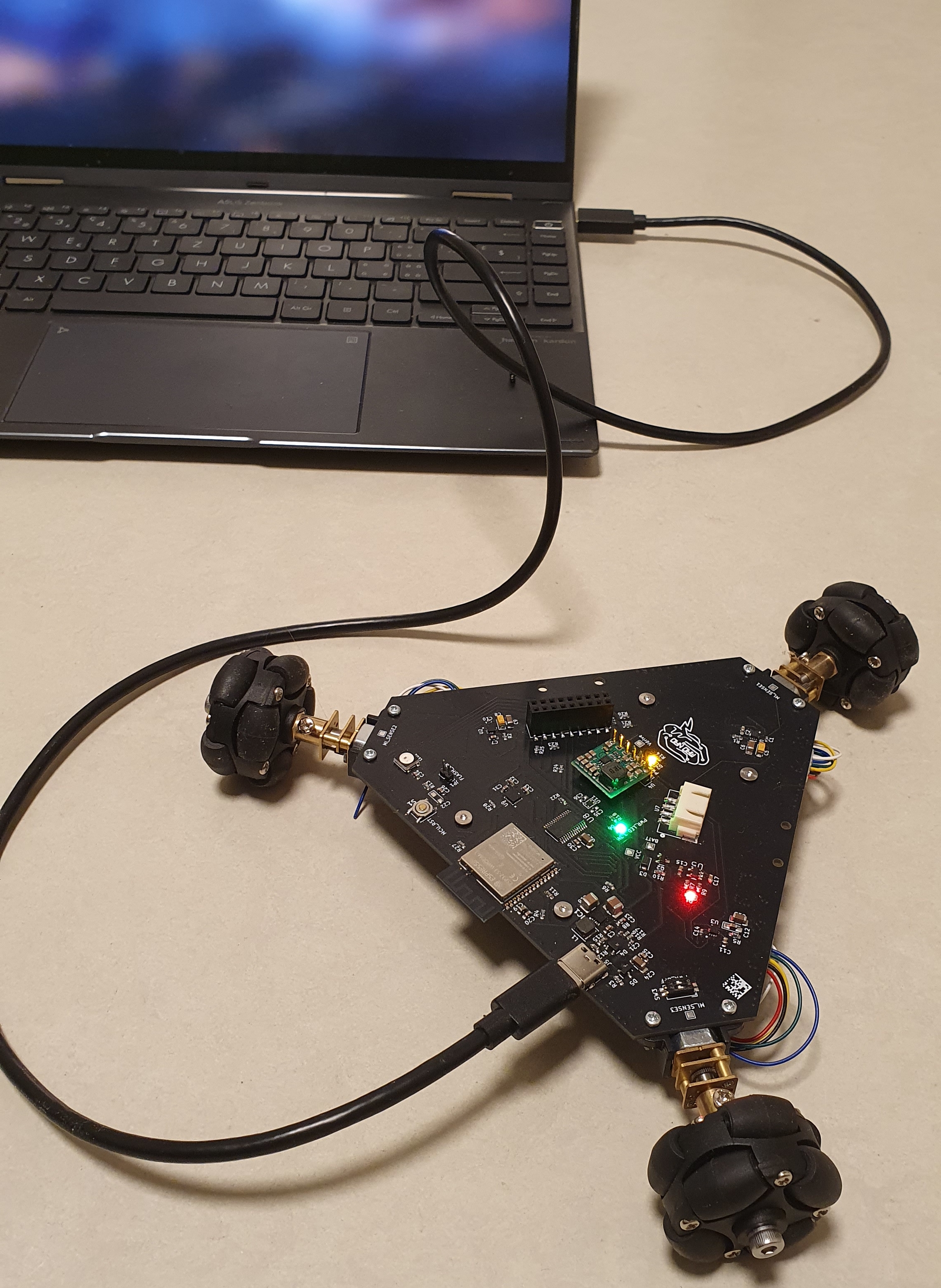
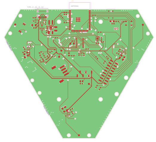
Mad Bot is an open-source printed circuit board by Incomprehensible, from the Incomprehensible/Mad_Bot repository on GitHub, published under the MIT licence. It is a 4-layer board of 133.1 × 115.3 mm with 95 parts on 119 nets, routed with 1,270 tracks and 341 vias.
It is built around the ESP32-S3-WROOM-1-N8R8, MP6550GG-Z and RT6150BGQW, with the MCP73831T-2ACI/OT-HXY, MPU-6500 and WMM7027ATSN1-4/TR among its other parts. Its parts include 33 capacitors, 26 resistors, 12 ICs, 7 diodes and 5 connectors. It belongs with the robots and motor control boards and the ESP32 boards of this library.


Exploratory project in Embedded Robotics and Swarm Algorithms
Warning: This is an ongoing project, and the repository is under construction!
Note: Software support for some features is still in progress.
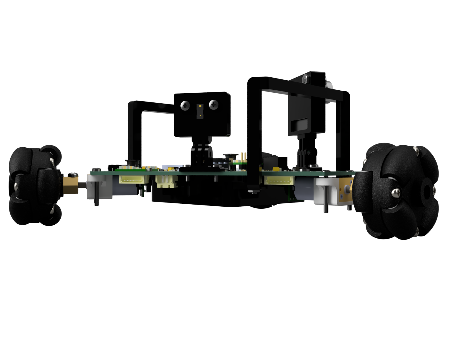 | 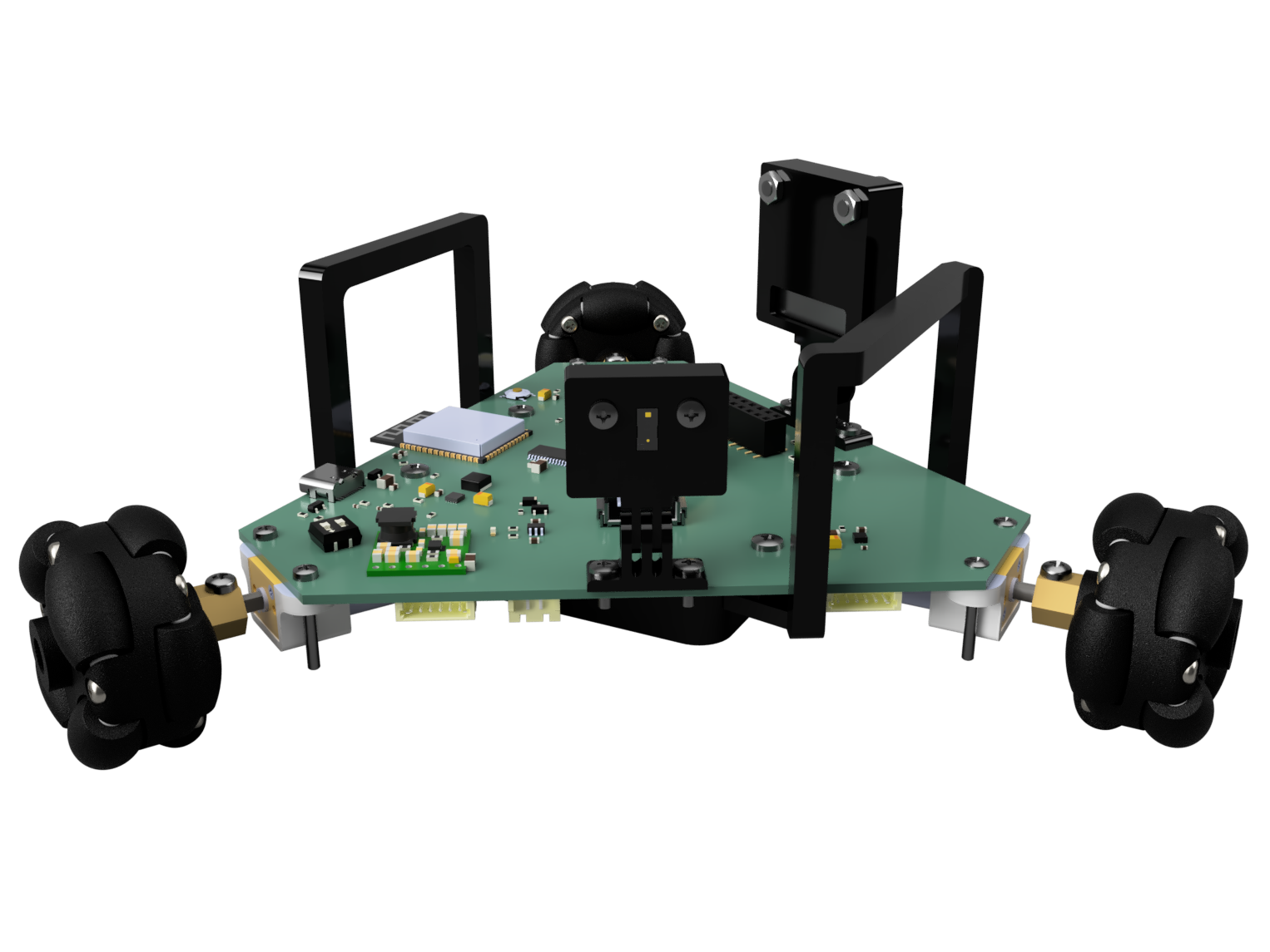 |
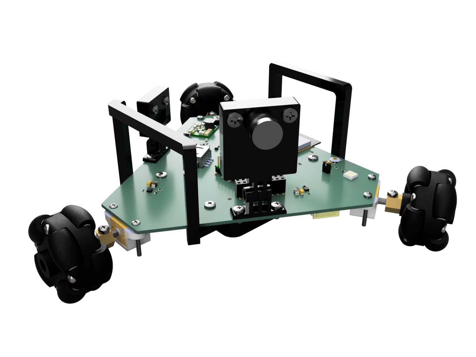 | 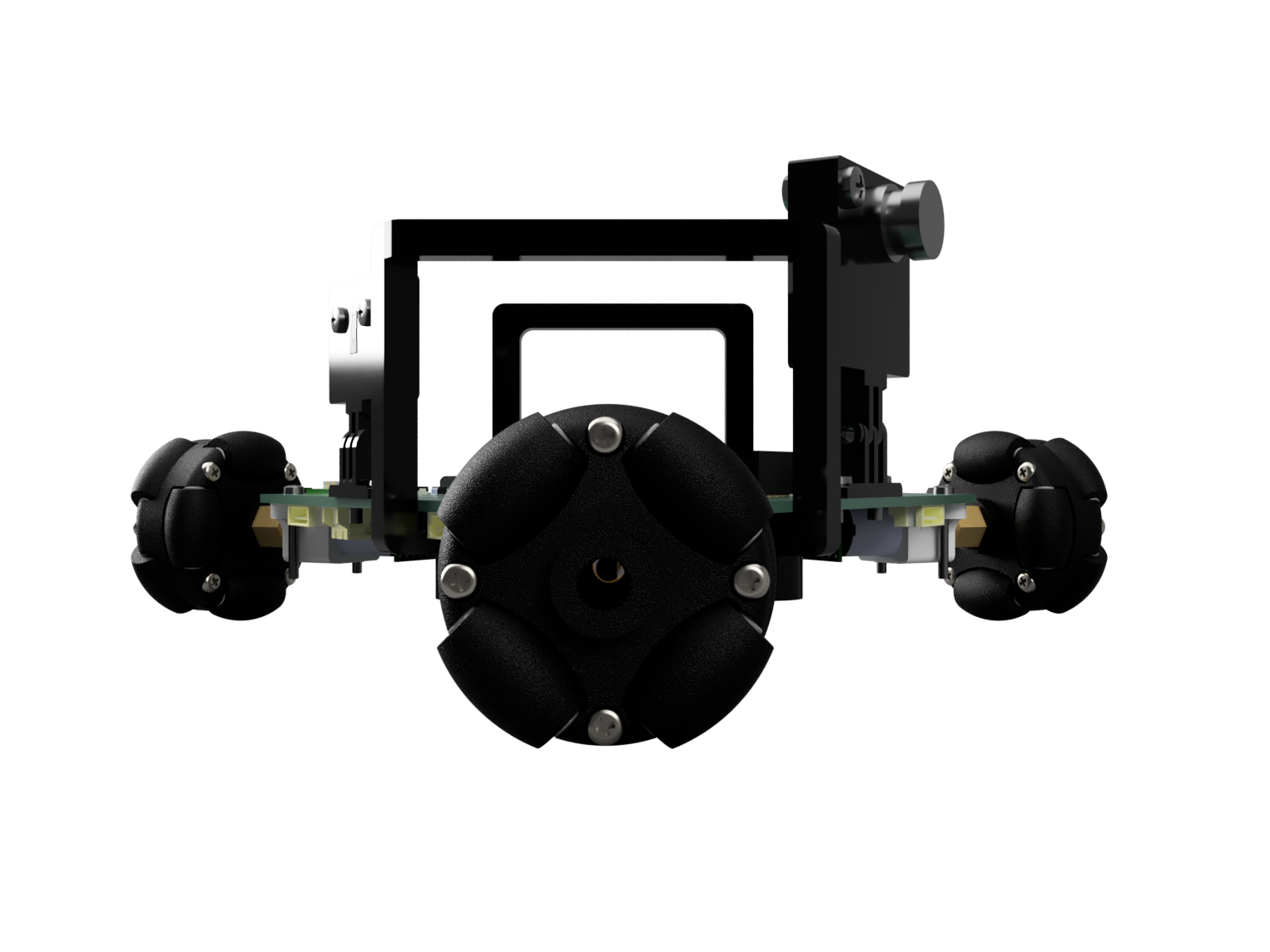 |
| Robot | Wheel |
|---|---|
 |  |
| Forward movement | Backward movement | Rotation |
|---|---|---|
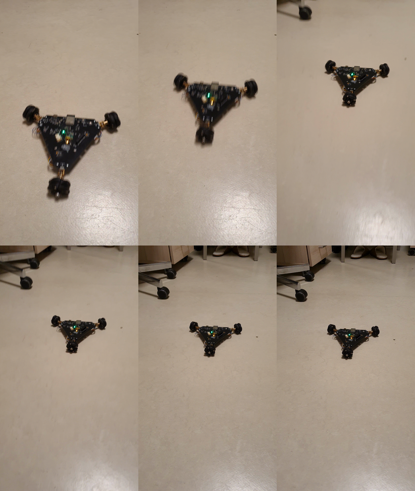 | 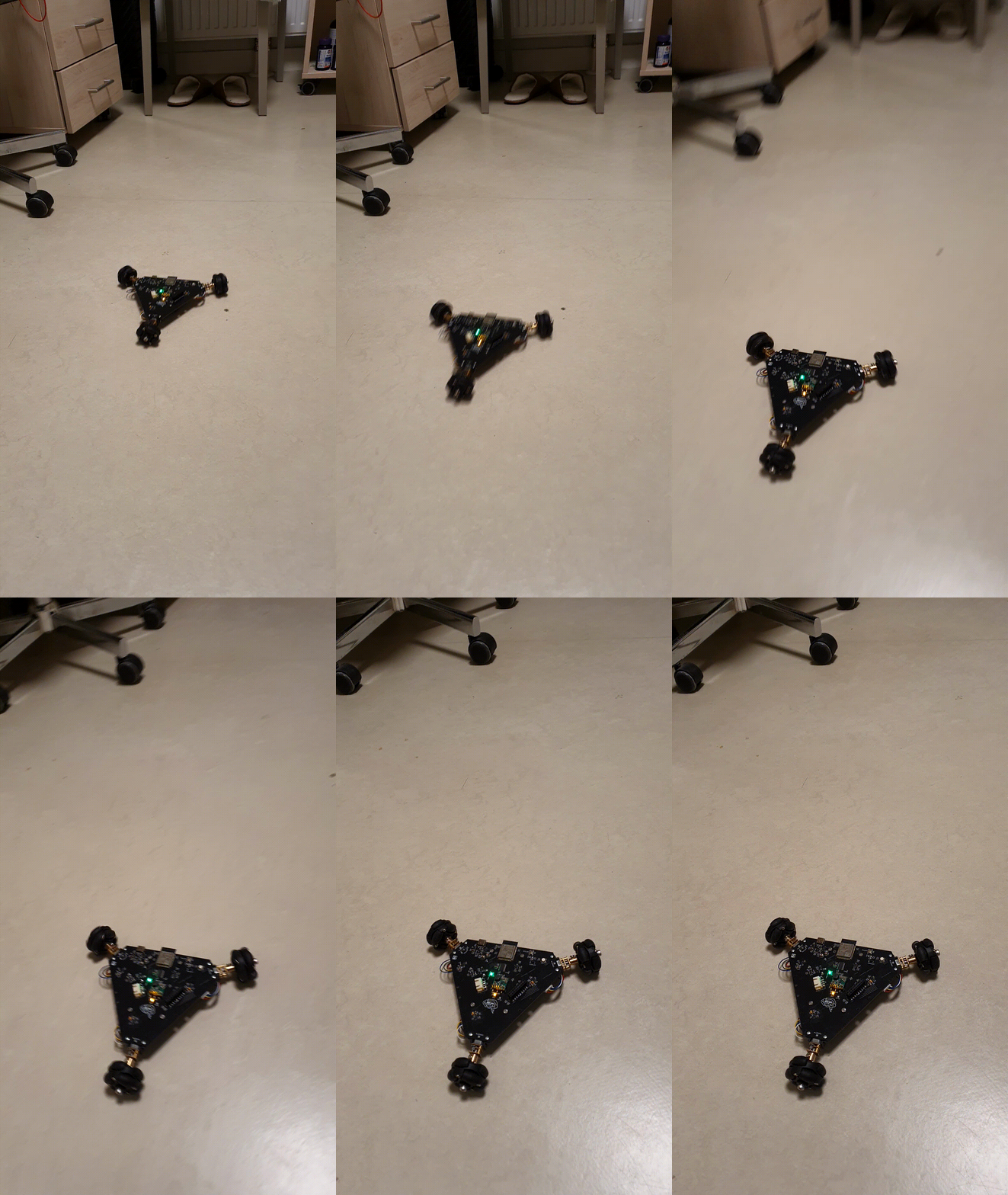 |  |
If you encounter issue like this building micro-ROS for the ESP32-S3 platform, edit libmicroros.mk file at line 110 to include esp32s3 as follows:
ifeq ($(IDF_TARGET),$(filter $(IDF_TARGET),esp32s2 esp32c3 esp32c6 esp32s3))This project takes inspiration from the following open-source projects:
| Qty | Value | Footprint | References |
|---|---|---|---|
| 10 | 0.1uF | Capacitor_SMD:C_0603_1608Metric_Pad1.08x0.95mm_HandSolder | C2, C7, C11, C20, C26, C30, C31, C33, C34, C36 |
| 10 | 250k | Resistor_SMD:R_0603_1608Metric_Pad0.98x0.95mm_HandSolder | R6, R8, R10, R21, R22, R23, R24, R25, R26, R28 |
| 5 | 10uF | Capacitor_SMD:C_1206_3216Metric_Pad1.33x1.80mm_HandSolder | C6, C9, C13, C24, C29 |
| 4 | 1uF | Capacitor_Tantalum_SMD:CP_EIA-3216-18_Kemet-A_Pad1.58x1.35mm_HandSolder | C5, C8, C12, C22 |
| 3 | 0.1nF | Capacitor_SMD:C_0402_1005Metric_Pad0.74x0.62mm_HandSolder | C1, C10, C14 |
| 3 | 8.5k | Resistor_SMD:R_0603_1608Metric_Pad0.98x0.95mm_HandSolder | R1, R2, R5 |
| 3 | EncoderConn | Mad_Bot:JST_S6B-ZR-SM4A-TF_1.5mm | J1, J2, J3 |
| 3 | MP6550GG-Z | Mad_Bot:IC12_MP6550_MNP | U1, U2, U3 |
| 2 | 1k | Resistor_SMD:R_0603_1608Metric_Pad0.98x0.95mm_HandSolder | R14, R18 |
| 2 | 20pF | Capacitor_SMD:C_0402_1005Metric_Pad0.74x0.62mm_HandSolder | C21, C23 |
| 2 | 22 | Resistor_SMD:R_0402_1005Metric_Pad0.72x0.64mm_HandSolder | R16, R17 |
| 2 | 4.7k | Resistor_SMD:R_0603_1608Metric_Pad0.98x0.95mm_HandSolder | R4, R11 |
| 2 | 4.7uF | Capacitor_SMD:C_0603_1608Metric_Pad1.08x0.95mm_HandSolder | C15, C17 |
| 2 | 47uF | Capacitor_SMD:C_1210_3225Metric_Pad1.33x2.70mm_HandSolder | C16, C18 |
| 2 | 5.1k | Resistor_SMD:R_0603_1608Metric_Pad0.98x0.95mm_HandSolder | R12, R15 |
| 2 | ESDA5V3L | Package_TO_SOT_SMD:SOT-23 | D4, D5 |
| 1 | 100nF | Capacitor_SMD:C_0603_1608Metric_Pad1.08x0.95mm_HandSolder | C3 |
| 1 | 10nF | Capacitor_SMD:C_0603_1608Metric_Pad1.08x0.95mm_HandSolder | C32 |
| 1 | 150k | Resistor_SMD:R_0603_1608Metric_Pad0.98x0.95mm_HandSolder | R13 |
| 1 | 1M | Resistor_SMD:R_0603_1608Metric_Pad0.98x0.95mm_HandSolder | R3 |
| 1 | 2.2uH | Mad_Bot:FNR4020S2R2MT | L1 |
| 1 | 22 | Resistor_SMD:R_0603_1608Metric_Pad0.98x0.95mm_HandSolder | R27 |
| 1 | 22uF | Capacitor_SMD:C_0603_1608Metric_Pad1.08x0.95mm_HandSolder | C19 |
| 1 | 2k | Resistor_SMD:R_0603_1608Metric_Pad0.98x0.95mm_HandSolder | R7 |
| 1 | 470 | Resistor_SMD:R_0603_1608Metric_Pad0.98x0.95mm_HandSolder | R9 |
| 1 | ArducamOV2640 | Mad_Bot:Arducam_Socket_2x09_P2.54mm_Vertical_SMD | U10 |
| 1 | BATT | TestPoint:TestPoint_Pad_1.5x1.5mm | TP5 |
| 1 | C | Capacitor_SMD:C_0603_1608Metric_Pad1.08x0.95mm_HandSolder | C35 |
| 1 | CHRG_LED | LED_SMD:LED_0603_1608Metric_Pad1.05x0.95mm_HandSolder | D1 |
| 1 | D_Schottky | Diode_SMD:D_SOD-123F | D3 |
| 1 | ESP32-S3-WROOM-1-N8R8 | Mad_Bot:XCVR_ESP32S3WROOM1N8R8 | U6 |
| 1 | Flash_En | Mad_Bot:Flash_Jumper_1x02_P2.00mm_Vertical | JP1 |
| 1 | LOGO | NadSilk:brain_logo | G*** |
| 1 | LiPo | Mad_Bot:JST_S2B-PH-SM4-TB_LF__SN_ | J4 |
| 1 | MCP73831T-2ACI_OT | Mad_Bot:SOT95P280X145-5N | U5 |
| 1 | MCU_RST | Mad_Bot:PTS526SK15SMTR2LFS | S1 |
| 1 | MI_SENSE1 | TestPoint:TestPoint_Pad_1.5x1.5mm | TP1 |
| 1 | MI_SENSE2 | TestPoint:TestPoint_Pad_1.5x1.5mm | TP2 |
| 1 | MI_SENSE3 | TestPoint:TestPoint_Pad_1.5x1.5mm | TP3 |
| 1 | MPU-6500 | Mad_Bot:QFN24_3X3X0P9_MPU6500 | U9 |
| 1 | PCA9685PW_118 | Mad_Bot:SOP65P640X110-28N | U8 |
| 1 | PWROFF_Switch | Mad_Bot:DV7SA-02F-01_SW_DIP_SPSTx02_Slide | SW3 |
| 1 | PWR_LED_3.3V | LED_SMD:LED_0805_2012Metric_Pad1.15x1.40mm_HandSolder | D6 |
| 1 | PWR_LED_6V | LED_SMD:LED_0805_2012Metric_Pad1.15x1.40mm_HandSolder | D2 |
| 1 | Q_PMOS_GSD | Package_TO_SOT_SMD:SOT-23 | Q2 |
| 1 | RT6150BGQW | Mad_Bot:SON50P250X250X80-11N-D | IC1 |
| 1 | Reserv | Capacitor_SMD:C_0603_1608Metric_Pad1.08x0.95mm_HandSolder | C25 |
| 1 | TYPE-C-31-M-12 | Mad_Bot:HRO_TYPE-C-31-M-12 | J5 |
| 1 | U3V40F6 | Mad_Bot:U3V40F6_upd | U4 |
| 1 | VCC | TestPoint:TestPoint_Pad_1.5x1.5mm | TP4 |
| 1 | VL53L7CX | Mad_Bot:CONN_S4B-XH-SM4-TB_JST | U7 |
| 1 | Vdrive | TestPoint:TestPoint_Pad_1.5x1.5mm | TP6 |
| 1 | WMM7027ATSN1 | Mad_Bot:WMM7027ATSN1-4TR | U11 |
| 1 | WS2812B | Mad_Bot:WS2812B | LED1 |
It measures 133.1 × 115.3 mm and has 4 copper layers, 1.6 mm thick.
95 parts, built around the ESP32-S3-WROOM-1-N8R8, MP6550GG-Z, RT6150BGQW and MCP73831T-2ACI/OT-HXY. The full list of its parts is on this page, with links to each part's symbol and footprint where PCBKit's library has them.
From the Incomprehensible/Mad_Bot repository on GitHub, at the commit this page was made from: the board is pcb_design/Mad_Bot.kicad_pcb and its schematic schematics/Mad_Bot.kicad_sch. PCBKit opens the board in the browser, with nothing to install.
Its repository publishes it under the MIT licence: you may reuse it on that licence's terms (keep the author's notice, and for a copyleft licence share your changes alike).
sean618/MakerTiles
Modular STM32 electronic-tile system: hardware, firmware, the MicroBus + Field Protocol stack, and a Python daemon.


nickraymond/nereus_Pi_shield_ADIN2111
A Raspberry Pi Zero 2W shield built from a copy of the Sofar Bristlemouth mote: ADIN2111 two-port 10BASE-T1L with PoDL, powered from the bus, 5 V for the Pi, a 24 V payload port, and the Sofar mote's power path…

CopperPilot/CopperPilotDronePCB
Flight controller and airframe on one ESP32-S3 board. Fly it from any phone over its own Wi-Fi. Motor traces sized to IPC-2221 for about 3 A.

conol-ai/openwalkietalkie
OpenMicroDial firmware — Rust/embassy on SiFli SF32LB52 (LilyGo T-Display SF32 dev board)

Hung-Chi970104/chess_card
Business-card-scale RP2040 and e-paper hardware prototype for a portable chess interface.

Hung-Chi970104/gameboy
Compact RP2040 handheld-console hardware with custom controls, power circuitry, display interface, and fabrication files.
