

2 layers100 × 100 mm
RecurBOY
cyberboy666/recurBOY
a rpi0 video-instrument – created in collaboration with Guergana Tzatchkova
35 parts122GPL-3.0

 ImoogDi/LesScope10
Arduino based Dual Channel Scope for eurorack-modular synths
LesScope is an open-source printed circuit board by ImoogDi, from the ImoogDi/LesScope repository on GitHub. It is a 2-layer board of 38.1 × 109.2 mm with 56 parts on 52 nets, routed with 227 tracks and 33 vias.
It is built around the MCP6004-E/P and BAT46. Its parts include 21 resistors, 14 capacitors, 7 diodes, 6 connectors and 3 switches. It belongs with the audio and music and sensors and measurement boards and the AVR (ATmega, ATtiny) boards of this library.
Arduino based Dual Channel Scope for eurorack-modular synths.
Table of Contents
This eurorack-modul is designed for modular-synthesizers as dual channel scope modul.
Only two active parts are required to sample the signal at the jack-inputs.
The Arduino Nano samples the amplified signal on two 10-Bit A/D multiplexed inputs.
Sampled-data are then traced on the 1.3'' OLED display.
Dataentry and menu-selections are possible with that encoder Select.
AC/DC coupling is selectable for both channels on two switches.
Every channel has two jacks linked together for signal-input and routing to other inputs.
That signal on Channel1 is normalized to the Trigger input-jack.
With an additonal cable plugged into the Trigger jack a different trigger-signal can be used.
All parts are common available and DIY-friendly designed.
(Details see attached pictures)
Modul Frontpanel
Modul Backside
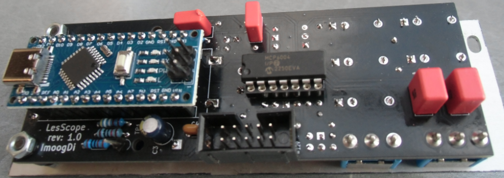
Modul Right side
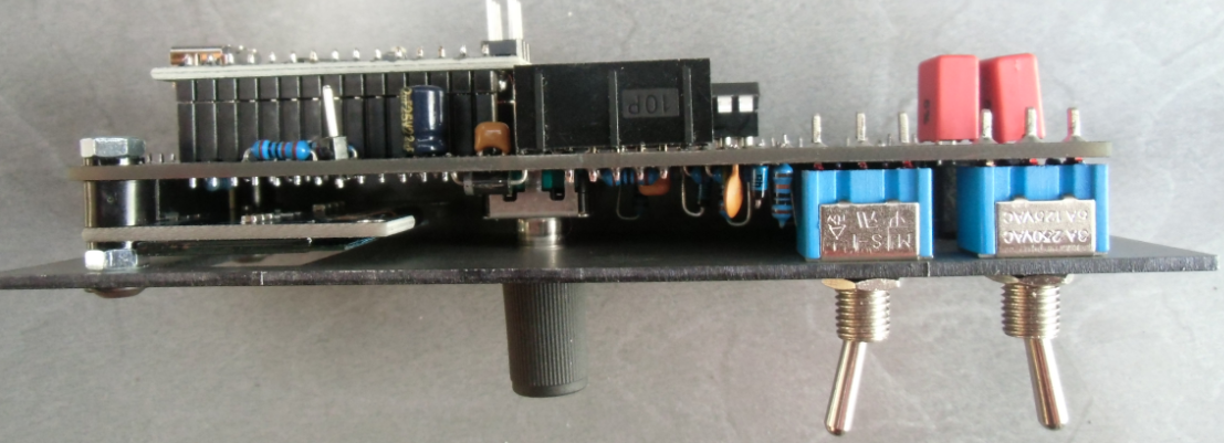
Modul Left side
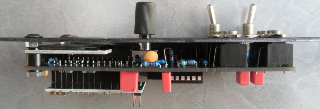
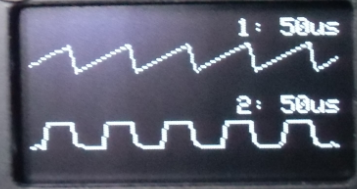
Dual Trace example
size:
height: 3VP (133,35mm)
width : 8HP ( 40,3mm)
depth : 35mm
power:
+5Volt, 0 mA
+12Volt, 45mA
-12Volt, 0 mA
display:
128x64 pixel 1.3inch OLED with SPI interface
MCU:
Arduino Nano V3.x ATmega 328P
Electrical features:
Rotary encoder with push-button.
Two separate channels with AC/DC-coupling.
Input Voltage 10Vp-p for both channels.
Menu selectable signal-amplification (1...4:Channel1; 1...2:Channel2).
Sampling-rate range: 50us...100msec on both channels.
Separate trigger-input (default linked to Channel1).
Measurement-capabilities (only on Channel1):
Frequency-measurement range: ~10Hz...~6000Hz.
Tuning-check range: C0(16.35Hz)...C8(4186.01Hz).
There are fife 3.5mm jacks available with following functions.
| Jack-Name | Function | Comment |
|---|---|---|
| Channel1 (two jacks) | Signal input for Channel1 | the two jacks are linked together and this signal is normalized to Trigger input. |
| Channel2 (two jacks) | Signal input for Channel2 | the two jacks are linked together. |
| Trigger | Signal input for Trigger | this signal is normalized to Channel1. |
Hardware:cc by-nc-sa 4.0 (details)
Software:licensed under GPL-3.0 (details)
| Qty | Value | Footprint | References |
|---|---|---|---|
| 5 | AudioJack2_SwitchT | Connector_Audio:Jack_3.5mm_QingPu_WQP-PJ398SM_Vertical_CircularHoles | J1, J2, J3, J4, J5 |
| 4 | 100nF | Capacitor_THT:C_Disc_D3.0mm_W1.6mm_P2.50mm | C4, C5, C6, C14 |
| 4 | 10K | Resistor_THT:R_Axial_DIN0204_L3.6mm_D1.6mm_P7.62mm_Horizontal | R7, R8, R17, R18 |
| 4 | BAT46 | Diode_THT:D_DO-35_SOD27_P7.62mm_Horizontal | D2, D3, D6, D7 |
| 3 | 10nF | Capacitor_THT:C_Disc_D3.0mm_W1.6mm_P2.50mm | C9, C12, C13 |
| 3 | 1K | Resistor_THT:R_Axial_DIN0204_L3.6mm_D1.6mm_P7.62mm_Horizontal | R11, R13, R21 |
| 3 | 4,7K | Resistor_THT:R_Axial_DIN0204_L3.6mm_D1.6mm_P7.62mm_Horizontal | R3, R16, R20 |
| 3 | 47K | Resistor_THT:R_Axial_DIN0204_L3.6mm_D1.6mm_P7.62mm_Horizontal | R5, R14, R15 |
| 2 | 10K | Resistor_THT:R_Axial_DIN0204_L3.6mm_D1.6mm_P2.54mm_Vertical | R9, R10 |
| 2 | 1uF | Capacitor_THT:C_Rect_L7.2mm_W3.0mm_P5.00mm_FKS2_FKP2_MKS2_MKP2 | C10, C11 |
| 2 | 2,2uF | Capacitor_THT:C_Rect_L7.2mm_W3.5mm_P5.00mm_FKS2_FKP2_MKS2_MKP2 | C1, C2 |
| 2 | 27nF | Capacitor_THT:C_Disc_D3.0mm_W1.6mm_P2.50mm | C7, C8 |
| 2 | BAT46 | Diode_THT:D_DO-35_SOD27_P2.54mm_Vertical_KathodeUp | D4, D5 |
| 2 | SW_SPDT | PCM_4ms_Switch:Switch_Toggle_SPDT_Mini_SolderLug | SW2, SW3 |
| 1 | 100K | Resistor_THT:R_Axial_DIN0204_L3.6mm_D1.6mm_P2.54mm_Vertical | R1 |
| 1 | 100K | Resistor_THT:R_Axial_DIN0204_L3.6mm_D1.6mm_P7.62mm_Horizontal | R2 |
| 1 | 1N5817 | Diode_THT:D_DO-41_SOD81_P7.62mm_Horizontal | D1 |
| 1 | 2.7K | Resistor_THT:R_Axial_DIN0204_L3.6mm_D1.6mm_P7.62mm_Horizontal | R12 |
| 1 | 22u | Capacitor_THT:CP_Radial_D5.0mm_P2.50mm | C3 |
| 1 | 27K | Resistor_THT:R_Axial_DIN0204_L3.6mm_D1.6mm_P7.62mm_Horizontal | R19 |
| 1 | 4,99K | Resistor_THT:R_Axial_DIN0204_L3.6mm_D1.6mm_P7.62mm_Horizontal | R6 |
| 1 | 47K | Resistor_THT:R_Axial_DIN0204_L3.6mm_D1.6mm_P2.54mm_Vertical | R4 |
| 1 | Arduino_Nano_v3.x | Module:Arduino_Nano | A1 |
| 1 | Conn_02x05_Odd_Even | PCM_4ms_Connector:Pins_2x05_2.54mm_TH_Europower | J6 |
| 1 | MCP6004 | Package_DIP:DIP-14_W7.62mm | U1 |
| 1 | OLED 1.3 128X64 SPI | Display:DisplayModule_DM_OLED13 | U2 |
| 1 | OSHW-Logo2_7.3x6mm_SilkScreen | Symbol:OSHW-Logo2_7.3x6mm_SilkScreen | REF_A |
| 1 | RotaryEncoder_Switch | Rotary_Encoder:RotaryEncoder_Alps_EC11E-Switch_Vertical_H20mm | SW1 |
| 1 | TestPoint | PCM_4ms_TestPoint:TestPoint_WireHole | TP1 |
It measures 38.1 × 109.2 mm and has 2 copper layers, 1.6 mm thick.
56 parts, built around the MCP6004-E/P and BAT46. The full list of its parts is on this page, with links to each part's symbol and footprint where PCBKit's library has them.
From the ImoogDi/LesScope repository on GitHub, at the commit this page was made from: the board is hw/LesScope.kicad_pcb and its schematic hw/Backplane.kicad_sch. PCBKit opens the board in the browser, with nothing to install.
Its repository states no licence, so its author keeps all rights: ask ImoogDi before reusing the design.
cyberboy666/recurBOY
a rpi0 video-instrument – created in collaboration with Guergana Tzatchkova

cyberboy666/sync_ope
effect send + sync restoring circuit - adapted from a gael jaton design

robsonsmartins/usbflashprog
A memory device programmer (Flash/EPROM/E2PROM) board and software, connected to PC by USB port.

mariusgreuel/EMS-Bus-Gateway
EMS Bus Gateway for Buderus Boilers to run EMS-ESP32

cyberboy666/i_n_c_u_r
a r_e_c_u_r video sampler extension circuit - adding knobs, cv and serial midi control

CosmicPi/CosmicPiV1.7PCB
PCB for Version 1.7 of the Cosmic Pi Hardware. Incremental changes from V1.6. This design is licensed under the CERN OHL V1.2

