2 layers53 × 91 mm
 imihajlow/discrete-clock1
A digital clock made of N-MOSFETs, diodes, and resistors.
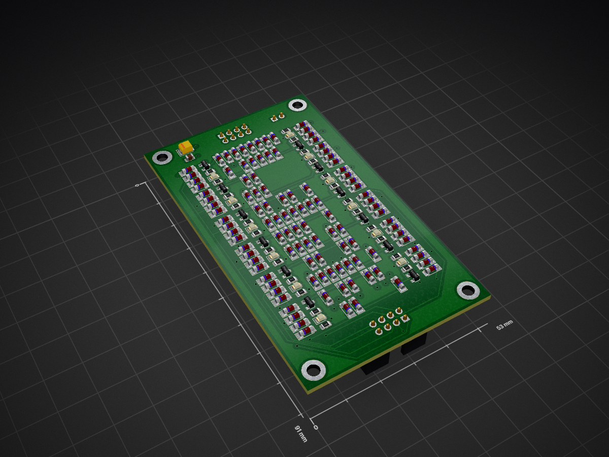
Decoder is an open-source printed circuit board by imihajlow, from the imihajlow/discrete-clock repository on GitHub. It is a 2-layer board of 53 × 91 mm with 166 parts on 54 nets, routed with 549 tracks and 94 vias.
Its parts include 121 diodes, 24 resistors, 12 transistors, 3 connectors and 2 capacitors.
| Qty | Value | Footprint | References |
|---|---|---|---|
| 109 | D | Diode_SMD:D_MiniMELF | D1, D10, D11, D100, D101, D102, D103, D104, D105, D106, D107, D108, D109, D110, D111, D112 +93 |
| 12 | 20k | Resistor_SMD:R_0805_2012Metric | R1, R2, R3, R4, R5, R6, R7, R8, R9, R10, R11, R12 |
| 12 | 2N7002 | Package_TO_SOT_SMD:SOT-23 | Q1, Q2, Q3, Q4, Q5, Q6, Q7, Q8, Q9, Q10, Q11, Q12 |
| 12 | 50 | Resistor_SMD:R_0805_2012Metric | R13, R14, R15, R16, R17, R18, R19, R20, R21, R22, R23, R24 |
| 12 | LED | LED_SMD:LED_0805_2012Metric | D40, D41, D42, D43, D44, D45, D116, D117, D118, D119, D120, D121 |
| 4 | MountingHole | MountingHole:MountingHole_3.2mm_M3_DIN965_Pad | H1, H2, H3, H4 |
| 1 | 0.1u | Capacitor_SMD:C_0805_2012Metric | C1 |
| 1 | 16u 10v | Capacitor_Tantalum_SMD:CP_EIA-3528-21_Kemet-B | C2 |
| 1 | In | Connector_IDC:IDC-Header_2x04_P2.54mm_Vertical | J1 |
| 1 | Out | Connector_IDC:IDC-Header_2x04_P2.54mm_Vertical | J2 |
| 1 | Power | Connector_PinHeader_2.54mm:PinHeader_1x02_P2.54mm_Vertical | J3 |
It measures 53 × 91 mm and has 2 copper layers, 1.6 mm thick.
166 parts. The full list of its parts is on this page, with links to each part's symbol and footprint where PCBKit's library has them.
From the imihajlow/discrete-clock repository on GitHub, at the commit this page was made from: the board is sch/decoder/decoder.kicad_pcb. PCBKit opens the board in the browser, with nothing to install.
Its repository states no licence, so its author keeps all rights: ask imihajlow before reusing the design.


imihajlow/discrete-clock
A digital clock made of N-MOSFETs, diodes, and resistors.


schlae/HardDriveInfo
Repair info and schematics for mostly older MFM hard drives

Thorinair/Avalon-Harmonics
A collection of Avalon Harmonics branded synthesizer modules.

doppelhub/Honda_Insight_LiBCM
Replacement BCM for G1 Honda Insight Lithium Conversion

OpenLogicEFI/Hardware
Hardware is based off an open source project called Speeduino by Josh Stewart.
