
2 layers290.1 × 130 mm

 imad-drs/STM32_BluePill_Pcb
A custom STM32F103C8T6 development board designed in KiCad
Stm32 design is an open-source printed circuit board by imad-drs, from the imad-drs/STM32_BluePill_Pcb repository on GitHub. It is a 2-layer board of 40.5 × 33 mm with 32 parts on 50 nets, routed with 175 tracks and 23 vias.
It is built around the AMS1117-3.3. Its parts include 13 capacitors, 5 resistors, 4 connectors, 2 ICs and 1 diode. It belongs with the STM32 boards of this library.
A custom STM32F103C8T6 development board designed in KiCad
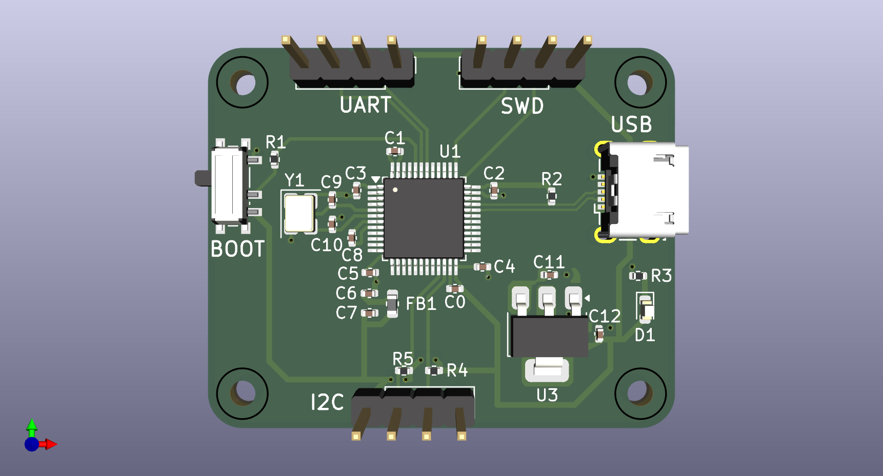
⚠️ Disclaimer: First PCB Project Please note: This is my very first custom PCB design! I reverse-engineered the popular "Blue Pill" board to design this custom circuit in KiCad. It was created as a personal learning exercise to understand the bridge between embedded software and physical hardware. While I put a lot of effort into following best practices, there may be errors. This project should not be used as an official hardware reference.
This repository contains the KiCad project files for a custom microcontroller development board based on the STM32F103C8T6 (ARM Cortex-M3).
One of the primary focuses of this project was understanding and implementing proper power delivery. Because microcontrollers switch states millions of times per second, they require instantaneous bursts of current. Traces and power supplies have inherent inductance and cannot deliver this current fast enough, potentially causing the system to crash.
To ensure stability, I implemented a strict decoupling strategy:
VDD and VBAT pin. These act as tiny, instant energy reservoirs to handle high-frequency switching..kicad_pro, .kicad_sch, .kicad_pcb).Schematic.pdf: Exported PDF of the logical circuit map.*Designed by Drias Imad Eddine *
| Qty | Value | Footprint | References |
|---|---|---|---|
| 5 | 100n | Capacitor_SMD:C_0402_1005Metric | C0, C1, C2, C3, C8 |
| 4 | 1k5 | Resistor_SMD:R_0402_1005Metric | R2, R3, R4, R5 |
| 4 | MountingHole | MountingHole:MountingHole_2.2mm_M2 | H1, H2, H3, H4 |
| 3 | Conn_01x04_Pin | Connector_PinHeader_2.54mm:PinHeader_1x04_P2.54mm_Vertical | J1, J3, J4 |
| 2 | 10n | Capacitor_SMD:C_0402_1005Metric | C5, C7 |
| 2 | 10p | Capacitor_SMD:C_0402_1005Metric | C9, C10 |
| 2 | 10u | Capacitor_SMD:C_0402_1005Metric | C4, C12 |
| 1 | 10k | Resistor_SMD:R_0402_1005Metric | R1 |
| 1 | 16Mhz | Crystal:Crystal_SMD_3225-4Pin_3.2x2.5mm | Y1 |
| 1 | 1u | Capacitor_SMD:C_0402_1005Metric | C6 |
| 1 | 22u | Capacitor_SMD:C_0402_1005Metric | C11 |
| 1 | AMS1117-3.3 | Package_TO_SOT_SMD:SOT-223-3_TabPin2 | U3 |
| 1 | FerriteBead | Inductor_SMD:L_0603_1608Metric | FB1 |
| 1 | RED | LED_SMD:LED_0603_1608Metric | D1 |
| 1 | STM32F103C8Tx | Package_QFP:LQFP-48_7x7mm_P0.5mm | U1 |
| 1 | SW_SPDT | Button_Switch_SMD:SW_SPDT_PCM12 | SW1 |
| 1 | USB_B_Micro | Connector_USB:USB_Micro-B_Wuerth_629105150521 | J2 |

pascallanger/DIY-Multiprotocol-TX-Module
Multiprotocol TX Module (or MULTI-Module) is a 2.4GHz transmitter module which controls many different receivers and models.

fossasia/pslab-hardware
PSLab Hardware Design and Schematics https://pslab.io


MaltWhiskey/Mega-Cube
16x16x16 PL9823 Cube with Teensy 4.0 and FlexIO driver


shamansystems/Cheap-FOCer-2
Low-Cost Motor Controller based on the VESC 6
It measures 40.5 × 33 mm and has 2 copper layers, 1.6 mm thick.
32 parts, built around the AMS1117-3.3. The full list of its parts is on this page, with links to each part's symbol and footprint where PCBKit's library has them.
From the imad-drs/STM32_BluePill_Pcb repository on GitHub, at the commit this page was made from: the board is stm32_design.kicad_pcb and its schematic stm32_design.kicad_sch. PCBKit opens the board in the browser, with nothing to install.
Its repository states no licence, so its author keeps all rights: ask imad-drs before reusing the design.