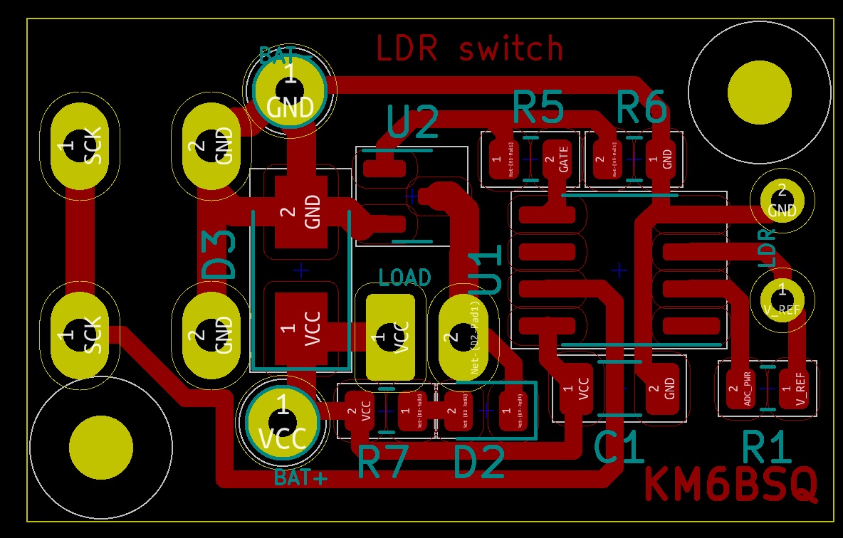
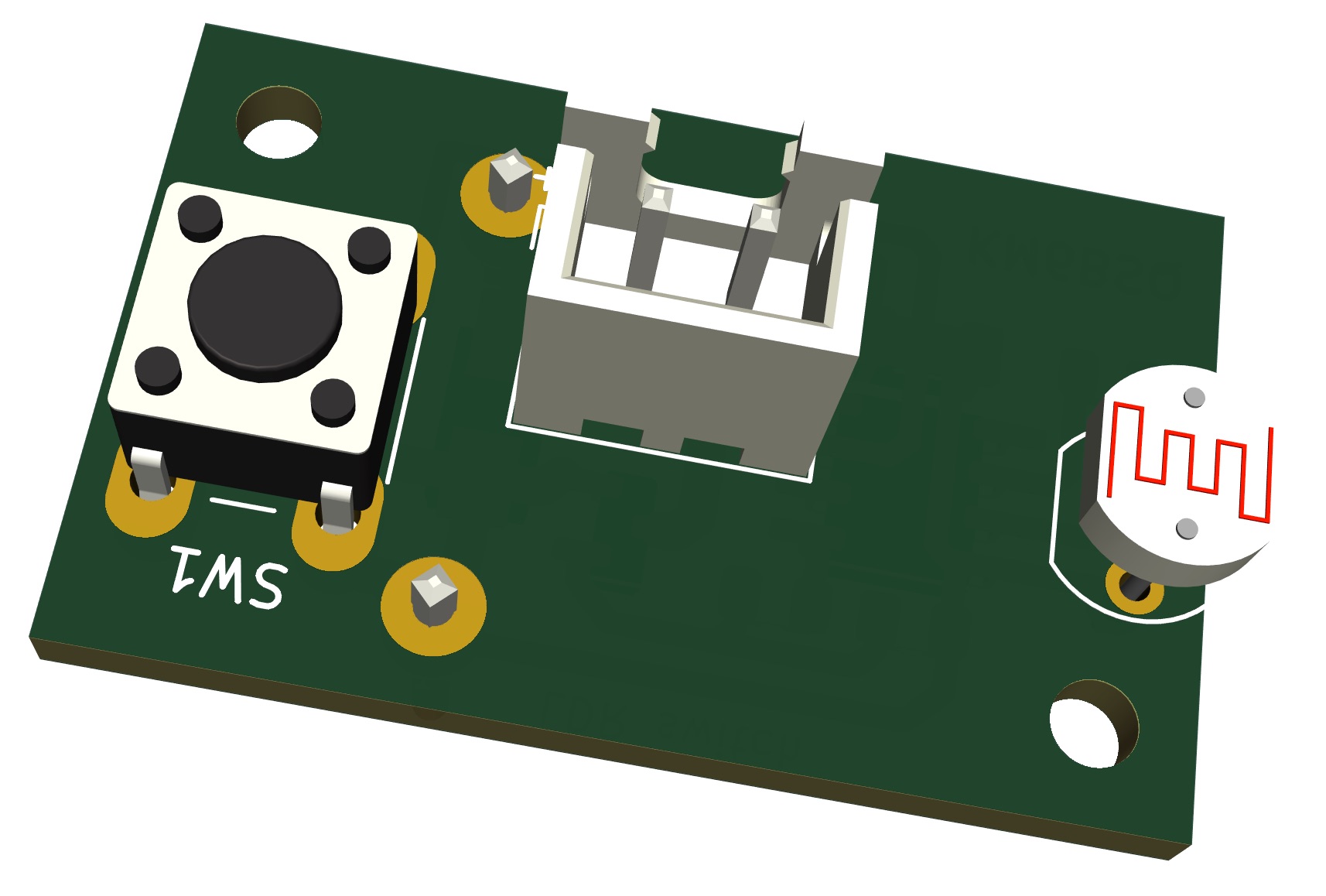
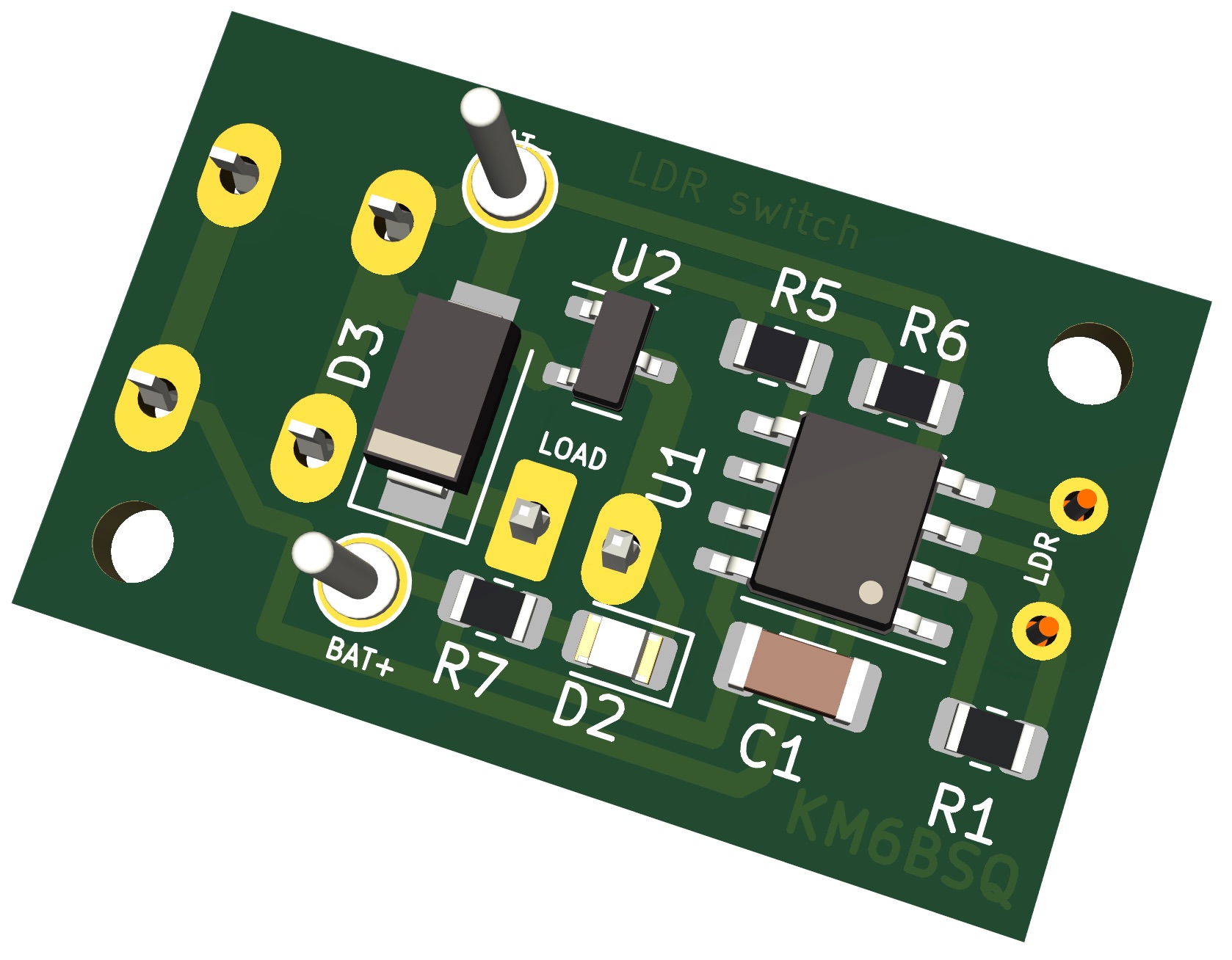
2 layers30.5 × 19 mm

 ikatkov/ldr-switch
Based on $0.60 Attiny13 MCU. 1kB flash, 256B ram.
Ldr switch is an open-source printed circuit board by ikatkov, from the ikatkov/ldr-switch repository on GitHub. It is a 4-layer board of 27.7 × 17.3 mm with 16 parts on 11 nets, routed with 78 tracks and 0 vias.
It is built around the ATTINY13-20SSU and AO3406. Its parts include 5 resistors, 3 connectors, 2 ICs, 2 diodes and 1 capacitor. It belongs with the AVR (ATmega, ATtiny) boards of this library.


Based on $0.60 Attiny13 MCU. 1kB flash, 256B ram.
It turns ON when it's dark (user configurable), stays ON for X hours, turns OFF, and waits till it's dark again. Intended to use with a battery, so it only consumes 5uA. Watch out for input power voltage. Min is 1.8V max is 5.5V. Max load current ~2A. Exceeds this and PCB traces will heat up and unsolder components. There is simple diode craw-bar reverse voltage protection for MCU.
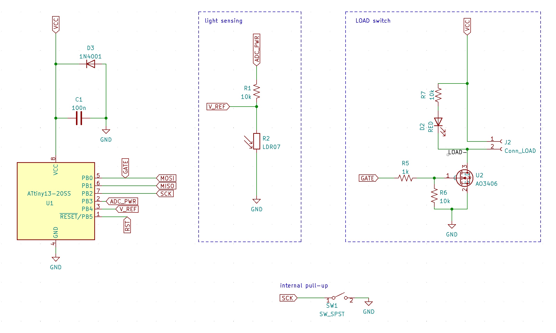
MCU sleeps all the time. Wakes up via watchdog interrupt every 4 sec to measure light. It powers the LDR/R voltage divider via the MCU pin, takes ADC measurements, and turns off the pin to save power. Compares measured light with the thresholds and goes into ON, OFF, or WAIT_FOR_RESET state. Depending on the state, it turns the load ON/OFF. A short button press wakes it from sleep, forcing it to measure light.
A long button press lets you set the auto-turn-off timer duration. Keep the button pressed and watch the LOAD blink. 1 blink == 1 hour, 2 blinks == 2 hours etc. Release the button once the desired number of hours is indicated.
When the timer is UP, the load turns OFF, and the MCU transitions into the WAIT_FOR_RESET state.
There are two light thresholds in the code.
WAIT_FOR_RESET is meant to capture the daytime reset so that the switch is only active once per day for X hours.
| Qty | Value | Footprint | References |
|---|---|---|---|
| 3 | 10k | Resistor_SMD:R_0805_2012Metric | R1, R6, R7 |
| 2 | MountingHole | MountingHole:MountingHole_2.2mm_M2 | H1, H3 |
| 1 | 100n | Capacitor_SMD:C_1206_3216Metric | C1 |
| 1 | 1N4001 | Diode_SMD:D_SMA | D3 |
| 1 | 1k | Resistor_SMD:R_0805_2012Metric | R5 |
| 1 | AO3406 | Package_TO_SOT_SMD:SOT-23 | U2 |
| 1 | ATtiny13-20SS | Package_SO:SOIC-8_3.9x4.9mm_P1.27mm | U1 |
| 1 | BAT+ | Connector_Pin:Pin_D1.0mm_L10.0mm | J4 |
| 1 | BAT- | Connector_Pin:Pin_D1.0mm_L10.0mm | J5 |
| 1 | Conn_LOAD | Connector_JST:JST_XH_B2B-XH-A_1x02_P2.50mm_Vertical | J2 |
| 1 | LDR07 | OptoDevice:R_LDR_5.1x4.3mm_P3.4mm_Vertical | R2 |
| 1 | RED | LED_SMD:LED_0805_2012Metric | D2 |
| 1 | SW_SPST | Button_Switch_THT:SW_PUSH_6mm | SW1 |
It measures 27.7 × 17.3 mm and has 4 copper layers, 1.6 mm thick.
16 parts, built around the ATTINY13-20SSU and AO3406. The full list of its parts is on this page, with links to each part's symbol and footprint where PCBKit's library has them.
From the ikatkov/ldr-switch repository on GitHub, at the commit this page was made from: the board is kicad/main.kicad_pcb and its schematic kicad/main.kicad_sch. PCBKit opens the board in the browser, with nothing to install.
Its repository states no licence, so its author keeps all rights: ask ikatkov before reusing the design.


aaronsilinskas/aura-prototype
A monorepo to prototype Aura Game Engine core features.

ikatkov/battery-capacity-meter
Vref pin on Arduino Pro Mini breakout board is not on any pin, solder a wire to capacitor between pins 12 and 13. To the pin13 end.