6 layers50 × 23 mm
Esp32p4amoled3.19
v-cu/dpf-load-monitor-wide
ESP32-P4 diagnostic display for VAG diesels — live DPF and engine data over CAN (UDS) on a 3.19" ultra-wide AMOLED. Firmware, KiCad files, BOM and 3D enclosure.
115 parts12

 iharhl/airy3
Air quality monitoring project based on ESP32C6 with BLE and Matter support + SwiftUI companion app
Airy is an open-source printed circuit board by iharhl, from the iharhl/airy repository on GitHub, published under the Apache-2.0 licence. It is a 2-layer board of 49 × 67 mm with 19 parts on 22 nets, routed with 108 tracks and 138 vias.
It is built around the 24AA64/P, CC0805KRX7R9BB104 and NCD0805R1. Its parts include 4 connectors, 3 resistors, 2 ICs, 1 capacitor and 1 diode. It belongs with the radio and wireless and sensors and measurement boards and the ESP32 and RISC-V boards of this library.



Airy is a from-scratch air quality monitor built around the Seeed Studio XIAO ESP32-C6. This embedded project covers the full chain end to end: component selection, schematic and PCB design, a custom 3D-printed enclosure, fault-tolerant FreeRTOS-based firmware, a rich BLE protocol, Matter smart-home integration, on-device history storage, and a native SwiftUI iOS companion app.
The device continuously measures PM1.0, PM2.5, PM4.0, PM10, CO2, VOC, NOx, temperature, and humidity using a Sensirion SEN66 sensor. In its default BLE mode, Airy streams live readings to the iOS app, syncs the RTC, exposes device maintenance commands, and buffers approximately 24 hours of offline history in external EEPROM for later download. The app merges live and historical samples into a 24-hour trend and computes the Air Quality Index from the raw measurements based on the EPA (Environmental Protection Agency) guidelines.
For smart-home integration, Airy can be switched into Matter mode and commissioned into Matter-compatible ecosystems such as Apple Home or Home Assistant.
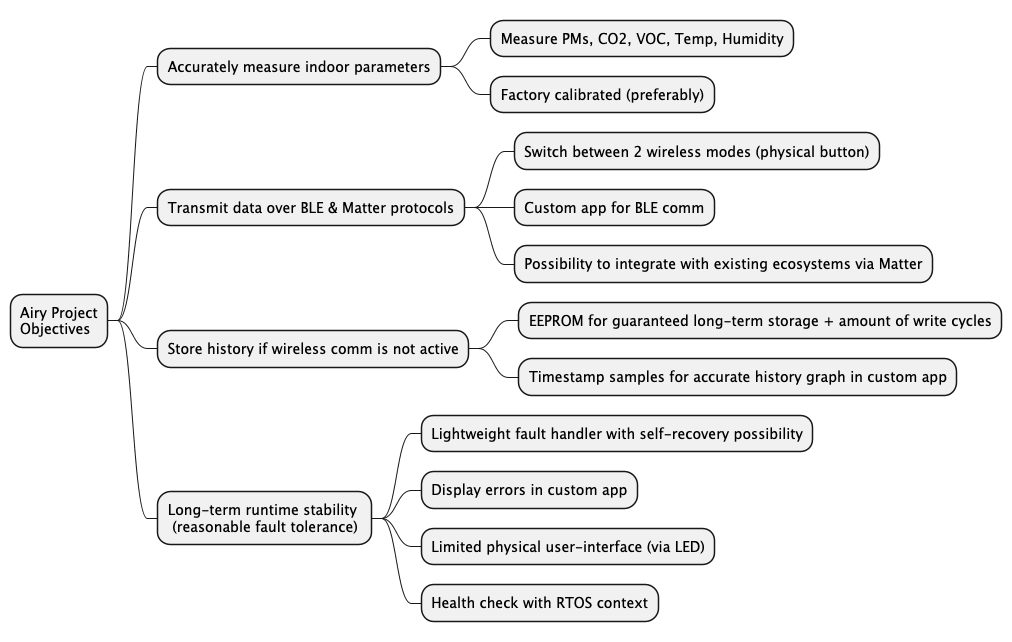
The project began with a clear definition of requirements and objectives, mapped out below. Based on these objectives, the appropriate hardware and software were selected.
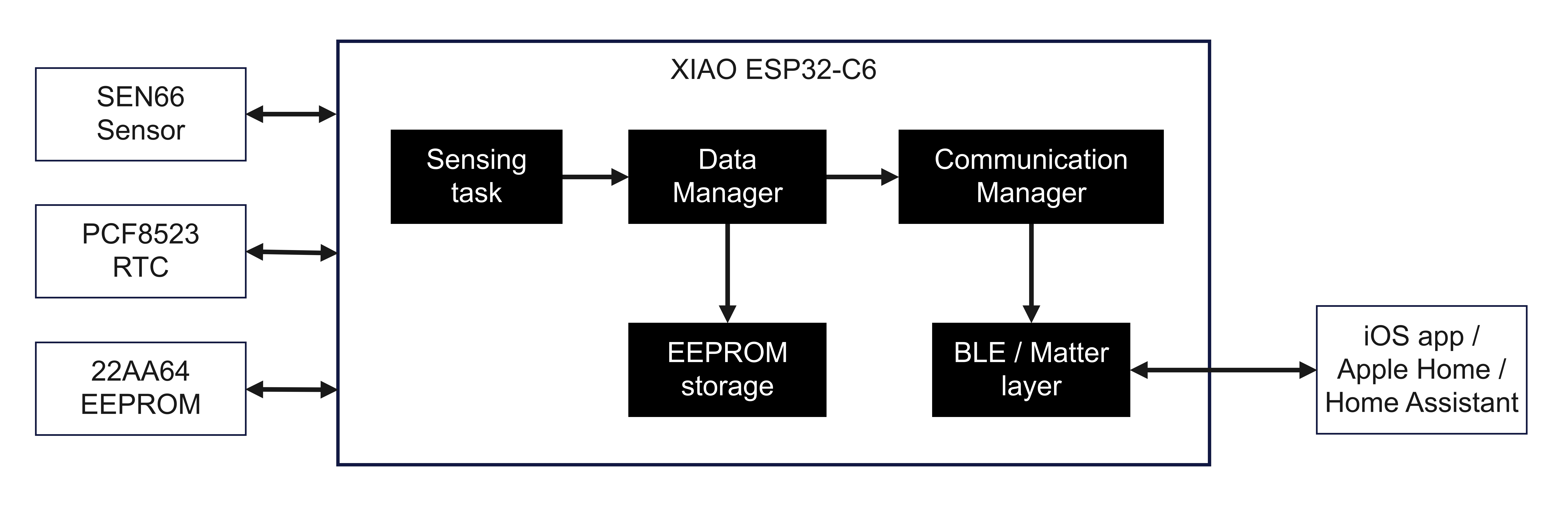
At its core, the Airy project consists of two primary components: ESP32-C6 firmware and a custom iOS BLE application. The high-level system architecture is illustrated below:
The device supports two mutually exclusive connectivity modes. The active mode is selected at boot and can be toggled using a button gesture:
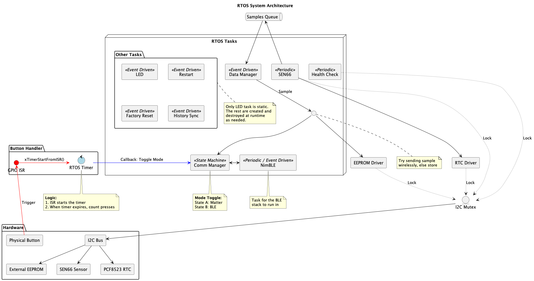
The rough RTOS-level architectural overview is defined in
rtos-architecture.puml, and displayed
in the image below.
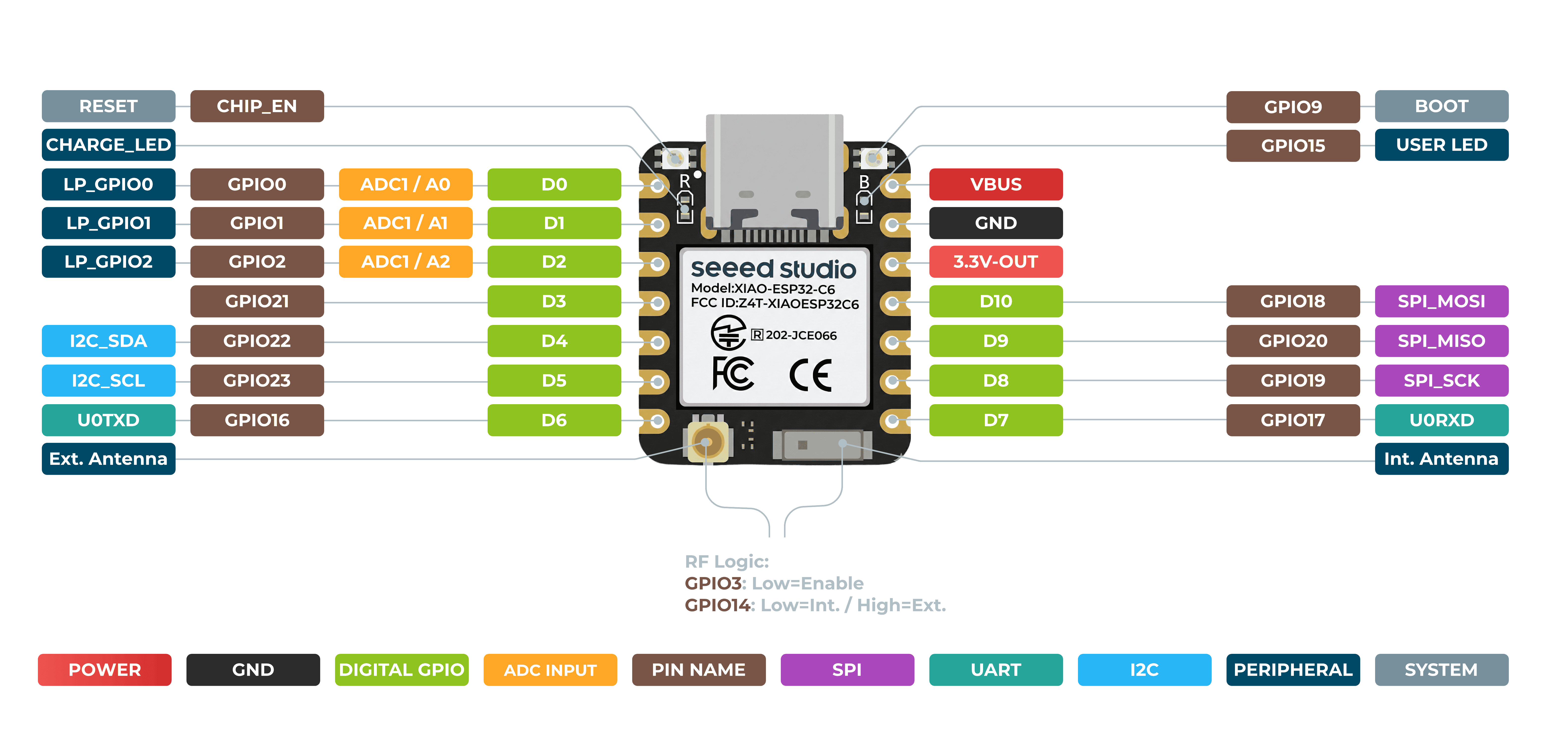
The brain is a Seeed Studio XIAO ESP32-C6 module. The ESP32-C6 is a 32-bit RISC-V SoC that, importantly for this project, carries the two radios Airy needs and natively supports the Matter protocol:
The XIAO form factor was chosen because it is tiny, easy to solder on the carrier PCB, and exposes enough GPIO for this design while keeping the BOM trivial. On top of that, the module has an on-board ceramic antenna which removes the need to use an external antenna. The signal strength with the ceramic antenna is quite mediocre, but good enough for the in-house use case.
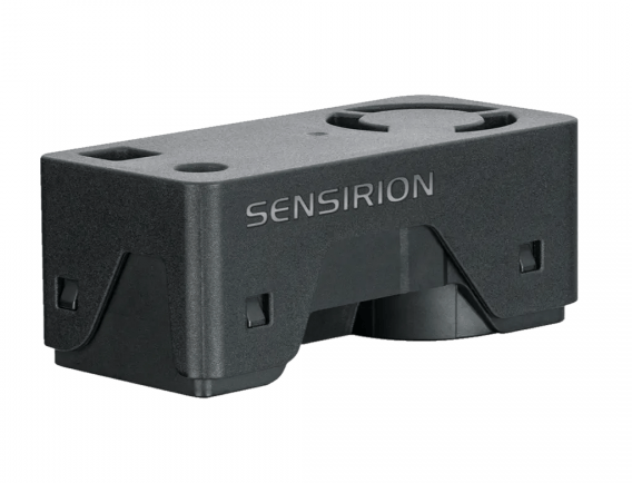
The SEN66 is the heart of the device. Choosing this particular module, despite its high price point, was guided by the fact that it combines PM, NDIR CO2, and metal-oxide gas sensors all in one factory-calibrated I2C package:
| Metric | Units | Raw scaling | Measurable range |
|---|---|---|---|
| PM1.0 | µg/m³ | / 10 | 0–1000 |
| PM2.5 | µg/m³ | / 10 | 0–1000 |
| PM4.0 | µg/m³ | / 10 | 0–1000 |
| PM10 | µg/m³ | / 10 | 0–1000 |
| Humidity | %RH | / 100 | 0–100 |
| Temperature | °C | / 200 | −10 to +50 |
| VOC | index | / 10 | 1–500 |
| NOx | index | / 10 | 1–500 |
| CO2 | ppm | — | 0–40000 |
Additionally, the sensor package provides:
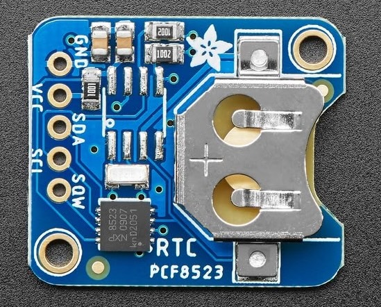
Every stored sample needs a timestamp, otherwise a 24-hour history chart is meaningless after a power cycle. An NXP PCF8523 I2C RTC breakout (Adafruit PCF8523) fills this role. A CR1220 coin cell on the breakout board keeps the clock running when the device loses main power, so timestamps remain accurate across reboots.
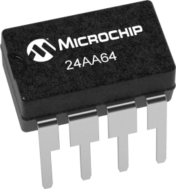
When the device is running unconnected, its readings need persistent storage. A Microchip 24AA64 serial EEPROM (64 Kbit = 8 KiB) provides that buffer.
The chip is organized as 256 pages of 32 bytes each, which fits one packed
sensor sample per page (sen66_sample_s is 24 bytes, leaving 8 bytes unused).
It is a simple, low-cost, low-power serial memory that needs no wear-leveling driver
(the circular-log strategy in the firmware handles endurance at a higher level).
The device has a deliberately minimal physical UI: one tactile pushbutton and one red indicator LED.
The "carrier" board was designed in KiCad. It is intentionally simple — the XIAO module carries the MCU and radios, so the carrier board only has to route the shared I2C bus, the pull-ups, the button, the indicator LED, and the sensor/RTC/EEPROM connections.
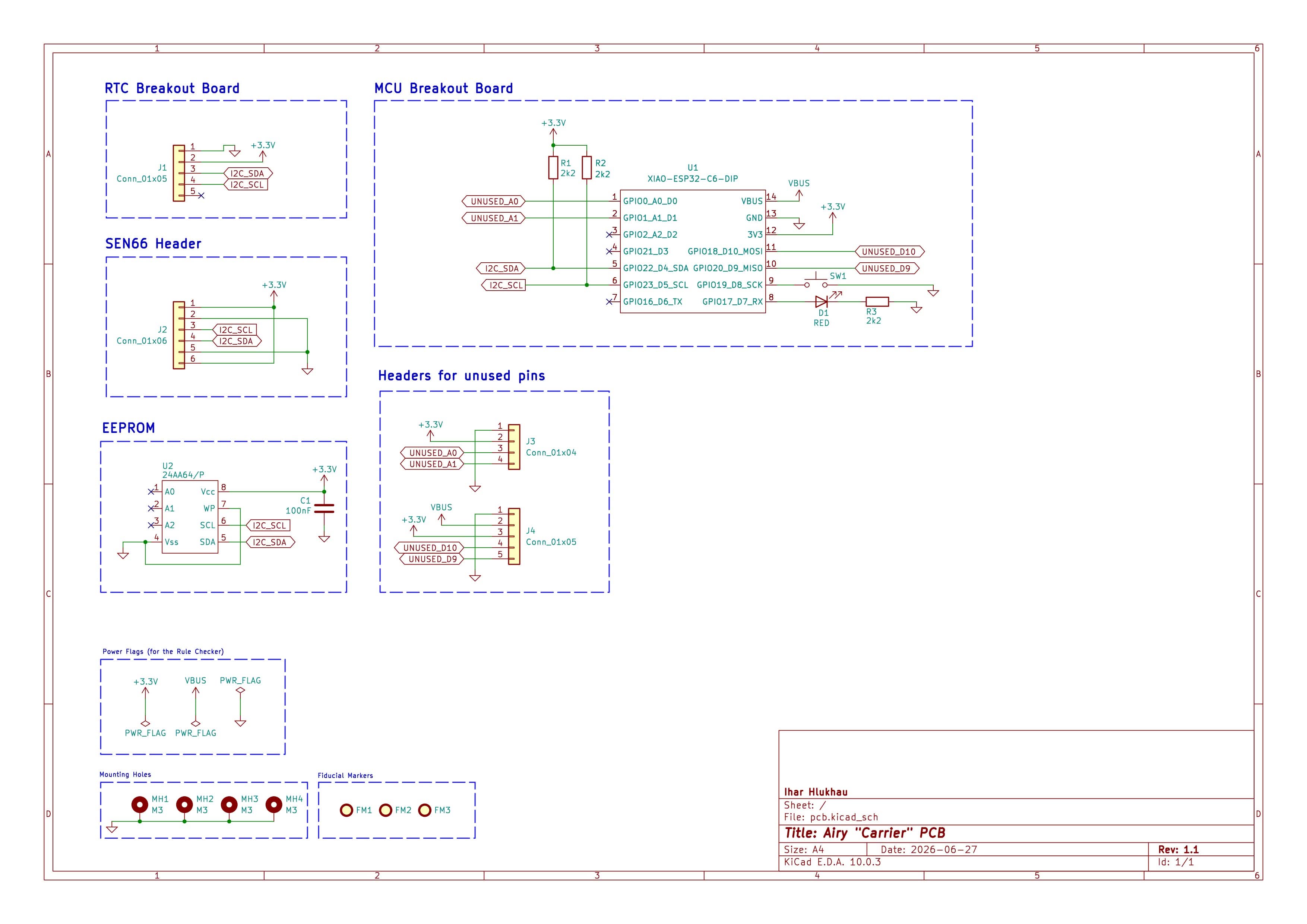
KiCad project files, including schematic and layout, are under pcb/.
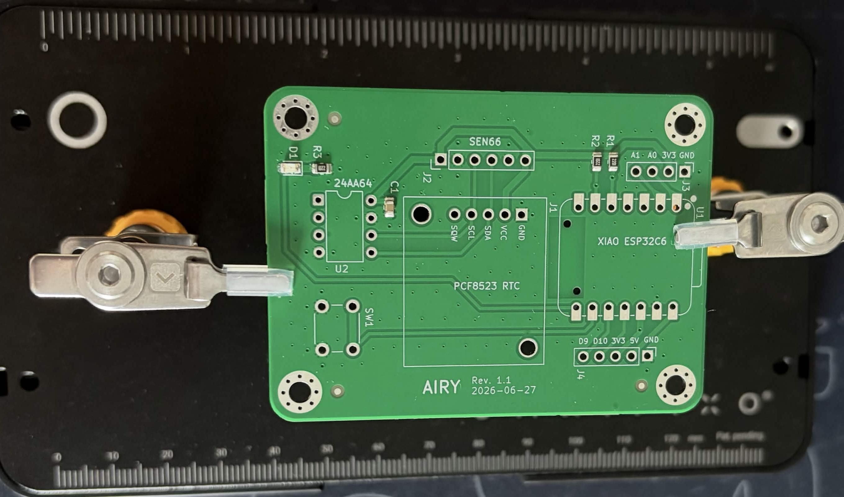
PCB manufacturing service was ordered from JLCPCB; the received board is shown below:
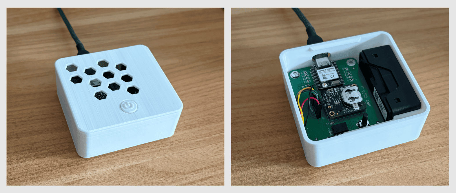
The enclosure was designed in Autodesk Fusion 360 and 3D-printed using a
Creality Ender-3 S1 printer.
I imported the .step files of the PCB (generated from KiCad) and the
SEN66 sensor (from the Senserion website) to aid the design. See the snapshot below.
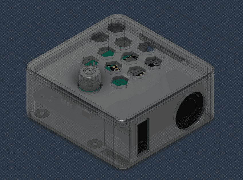
The final 3D model consists of three parts: base of the enclosure, the lid, and the knob. The box is 76.7 x 73.0 mm in size, with a height of approx 33 mm. The hole for the knob has tight tolerance, in combination with barely protruding from the case and the way it grabs the stem / actuator of the button, it produces an accurate and satisfying click every time.
STEP file of the enclosure is placed under enclosure/.
The firmware is an ESP-IDF application built on FreeRTOS, structured into
clean layers: low-level drivers (i2c, sen66, eeprom, rtc, button,
led), managers that own policy (data_mngr, comm_mngr, history,
fault, health_check), and communication interfaces (ble_*,
matter_interface). Every module exposes a small *_init() plus a focused API,
and inter-module coupling goes through these headers rather than shared globals.
app_main() (src/app_main.c) initializes subsystems in
strict dependency order, because later modules assume earlier ones exist:
fault_init            -> fault log + restart bookkeeping (RAM only, no NVS yet)
led_init              -> indicator available for the rest of boot
nvs_flash_init        -> init NVS (auto-erase + retry on error)
fault_restore_log     -> pull persisted fault records back into RAM
i2c_master_init       -> shared bus + mutex
rtc_init              -> probe PCF8523, else fall back to software clock
eeprom_init           -> add 24AA64, recover write pointer from NVS
sen66_init            -> add SEN66, start measurement and spawn task
data_mngr_init        -> queue + data-processing task
comm_mngr_init        -> configure antenna, init BLE/Matter layer, bring up radio
button_init           -> GPIO ISR + click timer (non-fatal if it fails)
health_check_init     -> watchdog + periodic monitor
In debug builds a 5-sec delay is inserted right after NVS to give time to attach a serial monitor.
Stack sizes and priorities live in one place, src/tasks.h. Note that
when running in RTOS debug mode (see sdkconfig profiles),
the system stacks (ISR, Idle, Timer) are automatically increased to accommodate
the tracing overhead.
| Task | Stack (B) | Priority | Description |
|---|---|---|---|
| LED control | 2048 | 3 | Event-driven (queue) |
| Health check | 2048 | 3 | Periodic + WDT feed |
| Comm manager | 2048 | 3 | Event-driven (mode switch) |
| SEN66 sensor | 2048 | 5 | Periodic |
| Data manager | 2048 | 5 | Event-driven (queue) |
| Restart | 1024 | 5 | One-shot, created on demand |
| Factory reset | 2048 | 5 | One-shot, created on demand |
| History sync | 4096 | 6 | One-shot, created on demand |
Only the LED, sensor, data, comm, and health tasks are permanent. The restart, factory-reset, and history-sync tasks are created and destroyed at runtime, which keeps RAM usage low. History sync gets the largest stack and the highest priority because it is a data-transfer-heavy, latency-sensitive BLE operation that must not be starved by the slower sensor / data manager loop.
Communication between tasks is explicit:
src/i2c.c wraps ESP-IDF's new i2c_master driver and adds a
bus-level mutex needed for this design. The ESP-IDF driver is thread-safe per
call, but a sequence like "write a register address, wait, then read N bytes" must
be atomic against other tasks. i2c_bus_lock() / i2c_bus_unlock() bracket every
such sequence. The module also offers convenience helpers (i2c_master_write16,
i2c_master_write16_then_read) and an i2c_probe_device() used to detect whether
the device is actually present.
src/sen66.c is the largest driver and encapsulates all
sensor-specific logic:
0x0021 start
measurement, 0x0300 read values, 0x5607 fan cleaning). The driver writes a
command, waits the datasheet's execution time, then reads the response.sen66_process_frame() validates the CRC and byte-swaps big-endian
wire order into the little-endian sen66_sample_s.sen66_sample_s: a 4-byte UNIX timestamp (from the RTC), nine 16-bit metric
fields, and a trailing CRC-16 computed over the whole record.Maintenance operations – device reset, fan cleaning, reading the device status register – are exposed as public functions used by the command handler and the health monitor.
src/data_mngr.c is the traffic controller. Its task pulls
samples off the queue and does one of two things depending on whether a live link
is up:
comm_mngr (flushing any partially
accumulated average first so ordering is preserved).average_with_pending_sample()) and, once 16 samples have accumulated,
commit the averaged record to the EEPROM circular log.The running average is computed incrementally to avoid storing 16 full samples, and a fresh CRC-16 is computed for the averaged record before it is written. If the EEPROM is unavailable or a history transfer is in progress, the record is dropped and the failure is escalated. Queue statistics (received / dropped / depth) are tracked by the health monitor.
src/eeprom.c implements a circular log of averaged samples for the 24AA64
EEPROM IC:
sen66_sample_s (24 bytes, fitting in a single
32-byte page), written by eeprom_write_page() with the page-aligned address
prepended to the I2C write.s_eeprom_addr_ptr) advances by one page per write and
wraps at the end of the chip, so the newest ~256 records always overwrite
the oldest (mimics a ring buffer).EEPROM_NVS_SYNC_EVERY_N_PAGES (4) writes.nvs_recover_eeprom_state() restores the saved address pointer and
validates it (must be page-aligned and within the chip boundary), falling back
to zero if the stored value is corrupt.eeprom_read_page() is used exclusively by the history transfer task and
enforces the same page-alignment and range constraints.The sampling and averaging constants are designed together: the sensor task runs at 21.6 s, and the data manager averages 16 samples before committing. That gives 16 x 21.6 s ~ 5.76 min per stored entry, which is 250 entries per day – fitting within 8KB EEPROM for one full day of buffered history.
src/rtc.c initializes the PCF8523 hardware and provides the time
abstraction for the rest of the firmware. Some design details are worth mentioning:
bcd_to_bin() and
bin_to_bcd() convert to/from native integers, and the full register set is
converted to a UNIX timestamp using standard mktime / gmtime_r with the
process timezone pinned to UTC.The architectural highlight is that the external RTC is optional.
rtc_init() first probes for the PCF8523. If the chip is not present
(or later becomes unreadable), the firmware falls back to a
boot-relative software clock:
software time = RTC_BOOT_EPOCH_UNIX + seconds_since_boot + user_adjustmentRTC_BOOT_EPOCH_UNIX is a fixed epoch (2026-07-01). When the phone syncs
the real time over BLE, rtc_set_unix_time() both writes the hardware RTC (if
present) and updates the software offset, so timestamps stay consistent even if
a later hardware read fails. rtc_is_external_valid() lets the health monitor
report which clock source is actually in use.
src/comm_mngr.c presents a single, transport-agnostic API to the
rest of the firmware. It handles switching between BLE and Matter protocols
and abstracts the wireless communication logic so that the rest of the system
does not care which radio is active.
BLE is implemented on NimBLE and split across several files for clarity:
setup (ble_setup.c), advertising
(ble_adv.c), GAP event handling
(ble_event_handler.c), the GATT server
(ble_gatt_server.c), and a transport-facing interface
(ble_interface.c).
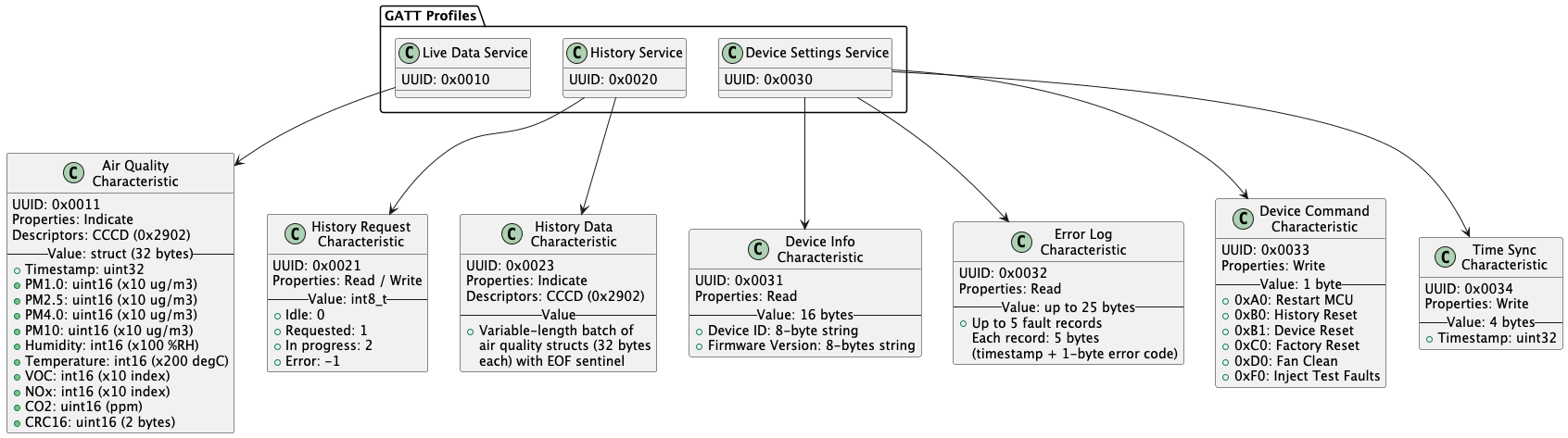
All services use a custom 128-bit base UUID with a 16-bit selector spliced in
(denoted by XXXX):
93e2XXXX-bce5-443f-a0b1-3462083b0323All the available services and characteristics, along with their properties, are
documented in ble-gatt.puml, shown below.
Design choices worth noting:
ble_wait_for_indication_done) enables
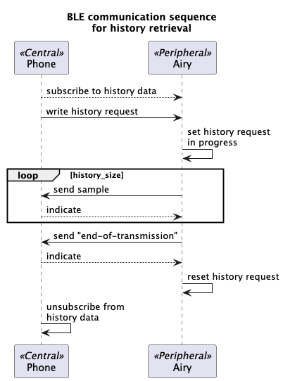
one-in-flight flow control.History download (src/history.c) is a small state machine
(IDLE -> REQUESTED -> IN_PROGRESS -> IDLE/ERROR) driven by the phone:
FF EF 00 00 is
transmitted so the app knows the stream is complete. The EEPROM page counter
is then reset on clean completion.The full handshake is diagrammed in
ble-history.puml.
src/matter_interface.cpp is the only C++ in the
firmware and wraps esp-matter. It builds a node with 3 endpoints shown
on the graph below.
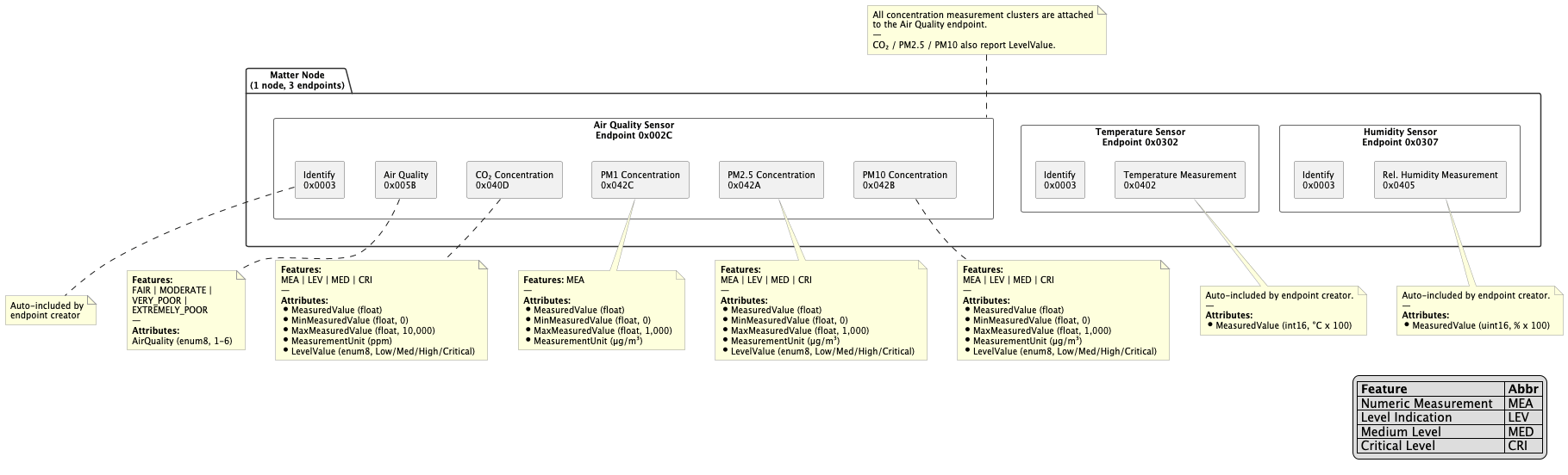
Raw SEN66 values are mapped to Matter semantics: concentration clusters get numeric values plus level indications (Low/Medium/High/Critical), and the overall Air Quality attribute is derived as the worst category across all pollutants. The module manages the commissioning window, attribute updates, tracks Wi-Fi/commission status for the health monitor, and supports a Matter fabric factory reset.
The choice to use three endpoints instead of one was due to Matter interoperability between platforms – Apple Home was not displaying all the clusters correctly if these were grouped under a single Air Quality Sensor endpoint. The code still contains an option for a single endpoint, but it is commented out. The current implementation provides a consistent display for both Apple Home and Home Assistant ecosystems.
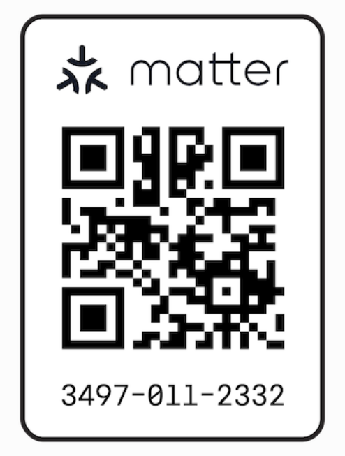
For commissioning, the default developer certificate was used. The QR code for this certificate is shown below.
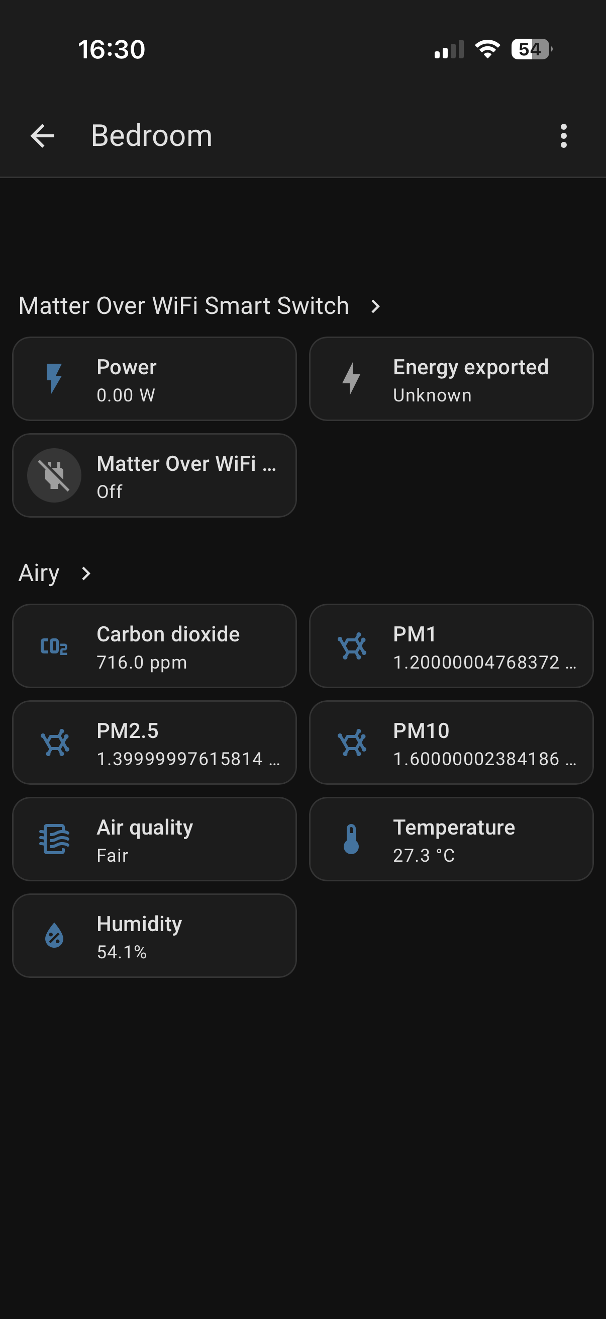
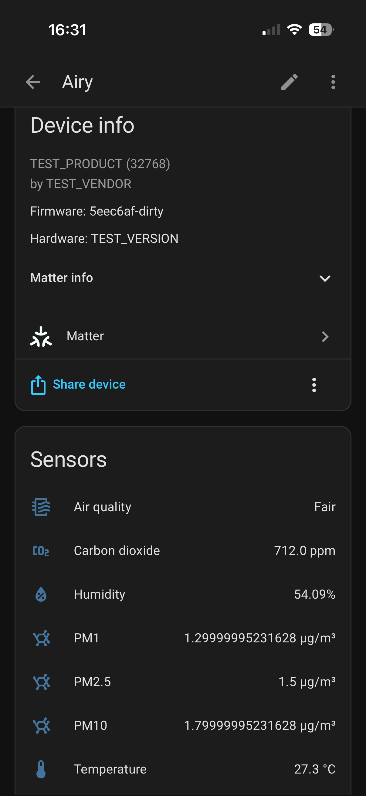
Here are screenshots of the Airy device commissioned in Home Assistant, where all metrics are grouped under one device:
Apple Home app displays metrics per endpoint on the main screen with concentration clusters located under Air Quality Sensor. Here is a video demo of the Airy device commissioned in Apple Home ecosystem:
https://github.com/user-attachments/assets/b454da02-5396-45ba-bc8d-8c492ae9b64d
A single button drives several actions through click counting
(src/button.c). The ISR debounces and increments an atomic
counter; 2 sec after the last press a timer callback interprets the total:
| Clicks | Action |
|---|---|
| 2 | Toggle BLE / Matter mode |
| 3 | Matter fabric reset |
| 4 | Full factory reset |
The same actions (plus more) are reachable over BLE via the Device Command
characteristic, dispatched by src/device_cmd.c:
| Command | Code | Effect |
|---|---|---|
| Restart | 0xA0 | Deferred MCU restart (lets the BLE write complete) |
| History reset | 0xB0 | Clear EEPROM history metadata + fault log |
| Device reset | 0xB1 | History reset + SEN66 device reset |
| Factory reset | 0xC0 | Reset SEN66, EEPROM and Matter, wipe NVS, restart |
| Fan clean | 0xD0 | Run SEN66 fan cleaning cycle |
| Inject fault | 0xF0 | Debug-only: push stub faults into the log |
Destructive/long operations (factory reset, restart) run in dedicated one-shot tasks so the BLE callback returns promptly and the operation gets a clean stack.
src/led.c turns the single LED into a status channel. Each action
maps to a distinct on/off sequence. A queue lets a newer pattern preempt one
that is mid-playback, and only the halt pattern loops forever. This gives the device
meaningful feedback if no debug interface is connected.
Two CRC algorithms are used (src/crc.c), each fit for purpose:
sen66_sample_s record end-to-end, so
corruption in the EEPROM or over the air is caught at both the firmware
(history read) and app (packet decode) sides.Implemented in src/fault.c and complemented by the health monitor.
An air quality monitor is expected to sit in a corner for weeks. The fault system was built around three goals:
Every fault is reported through one call:
fault_report(sys_fault_e subsystem, error_e error, esp_err_t esp_err);Reports are timestamped (via the RTC) and stored in a 20-entry ring buffer in
RAM, guarded by a mutex. Faults are categorized by subsystem (e.g., SEN66,
EEPROM, COMM, etc.) and by a specific error code. The ring buffer is
persisted to NVS just before any restart and restored on the next boot,
so the log is continuous across power cycles. The most recent five records are
exposed over the BLE Error Log characteristic for the app to display.
The key idea is that severity is a static property of the error code, decided
in one switch in fault_report(). Such an approach has some tradeoffs compared to
inspecting live subsystem state at report time, but it is much simpler to implement.
Errors fall into three classes:
Single glitches must not cause reboots. The FAULT_ESCALATE macro implements
consecutive-failure counting: each caller keeps a small counter, increments it
on failure, and only reports failure once the count crosses a threshold, then
resets it. A single success resets the counter to zero. This is used across drivers
(e.g., SEN66 reads, RTC reads/writes, BLE indications, etc.), so, for example, the
sensor has to fail three reads in a row before it is treated as faulted.
The restart mechanism uses RTC_NOINIT_ATTR variables, which survive
esp_restart() (they live in RTC RAM that is not zeroed on soft reset):
src/health_check.c is the periodic conscience of the
system. Its task subscribes to the Task Watchdog and feeds it every 3 sec, and
every 60 sec it runs a full sweep:
The health monitor also participates in fault reporting (e.g., heap corruption or low memory).
Error codes are grouped by subsystem, mirrored exactly in the iOS
FirmwareError model so the app can decode the Error Log characteristic:
| Code | Meaning |
|---|---|
| 2 | I2C bus initialization failed |
| 20 | FreeRTOS task creation failed |
| 40 | SEN66 did not become ready |
| 41 | SEN66 consecutive samples out of range |
| 42 | SEN66 consecutive I2C/CRC read failures |
| 43 | SEN66 device-status register reports an error |
| 60 | EEPROM I2C device add failed |
| 61 | NVS flash state error |
| 80 | Data queue creation failed |
| 81 | EEPROM write / drop persistent failure |
| 82 | History transfer start failed |
| 100 | Comm-manager event group creation failed |
| 101 | BLE init failure (from comm manager) |
| 102 | Matter init failure (from comm manager) |
| 103 | Wireless mode-switch persistence failed |
| 120 | Button ISR registration failed |
| 121 | Button click-timer creation failed |
| 140 | BLE stack initialization failed |
| 141 | BLE advertising start failed |
| 142 | BLE indication persistent failure |
| 143 | BLE MTU below minimum (244 bytes) |
| 160 | Health check: EEPROM NVS sync failed |
| 161 | Health check: heap corruption detected |
| 162 | Health check: critically low free heap |
| 180 | RTC I2C device add failed |
| 181 | RTC consecutive read failures |
| 182 | RTC consecutive write failures |
The companion app (ios-app/) is a native SwiftUI application
(Swift 6, iOS 17+) that receives raw BLE stream and presents a dashboard with an
Air Quality Index, historical charts, and device maintenance. Take a look at the demo
below:
https://github.com/user-attachments/assets/417c0d9c-ef65-4417-9c84-ebc311fbdae2
The app follows a service-oriented architecture. A handful of observable singletons own state and views react to them:
AppStateManager – the high-level app state machine.BLEManager – CoreBluetooth orchestration and the owner of three service
handlers.BLELiveDataServiceHandler, BLEHistoryServiceHandler, BLESettingsHandler
– one handler per GATT service, so each concern (live stream, history download,
settings/commands) is isolated.DataRepository – converts raw packets into scaled, AQI-scored storage entries.StorageManager – on-device persistent storage of metrics' history data.AppState drives which screen RootContentView shows. The rough overview of the
app's state flow can be found in
ios-app-state-flow.puml and is rendered below.
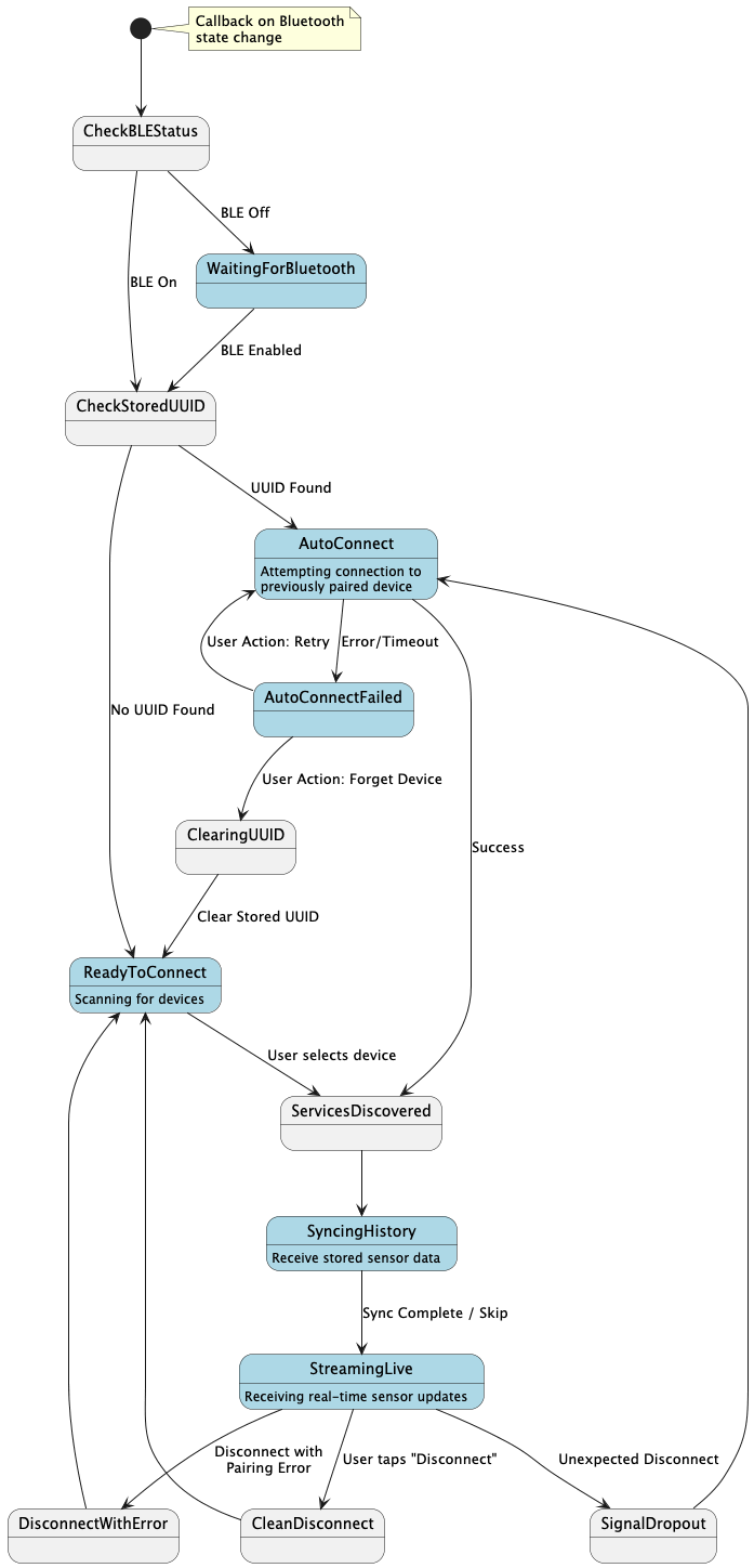
The exact states are:
waitingForBluetooth that covers the Bluetooth being off;autoConnect that silently reconnects to the last device (stored UUID) with a
9 sec timeout;autoConnectFailed that prompts user to retry or forget the device (erase stored UUID);readyToConnect that waits for user to start device discovery and
select the found airy device;syncingHistory that initiates History transfer protocol
and shows the download progress;streamingLive that listens to the live samples and displays the dashboard with metrics;error state is currently unused.BLEManager is a CBCentralManager/CBPeripheralDelegate. It scans for
peripherals whose name contains airy, connects, discovers services, and lazily
instantiates the three handlers once their characteristics are found. It uses the
exact same UUIDs as the firmware (base 93e2XXXX-bce5-443f-a0b1-3462083b0323).
The last-connected peripheral's UUID is remembered for auto-reconnect, and
cleared on factory reset / forget. Incoming values are routed by characteristic
UUID to the right handler.
The history handler kicks off a transfer by writing 0x01 to the History Request
characteristic, collects indication batches, and recognises the FF EF 00 00
EOF sentinel to finish (after which it transitions to live streaming). Pairing
edge cases (peerRemovedPairingInformation, encryptionTimedOut) route back to a
clean connect flow rather than an infinite retry.
AirQualityPacket mirrors the firmware's sen66_sample_s byte-for-byte and is
decoded straight from the received Data via MemoryLayout. DataRepository
then applies the same scaling factors as the SEN66 table
to produce actual values.
The firmware deliberately ships raw metrics; the app computes the Air Quality Index using the 2024 US EPA breakpoints. For each of PM2.5, PM10, VOC, and NOx it performs the standard EPA piecewise linear interpolation:
AQI = (AQI_high − AQI_low) / (C_high − C_low) x (C − C_low) + AQI_lowwith EPA-mandated rounding (PM2.5 to one decimal, PM10 to an integer). The overall index is the maximum of the four sub-indices (exactly how government agencies report a single AQI number). Each metric additionally has its own color indicators (Good → Hazardous) used for the gauges and charts.
StorageManager persists the trend as a JSON file (aq_history.json), loaded
into memory at launch and written atomically on a background task. Both the
live handler and the history handler funnel packets through the same DataRepository,
and timestamp acts as a unique storage id, discarding the duplicate samples.
A 24-hour retention window trims older entries, matching the device's ~1-day
EEPROM buffer.
The Settings screen issues the same maintenance commands the firmware understands (described in Device commands), each as a single-byte write to the Device Command characteristic:
run.sh is the developer entry point. It wraps idf.py but adds the
things this project needs on every invocation:
export.sh scripts.--release and --rtos-debug flags swap the sdkconfig overlay
between the debug, release, and heavy-RTOS-debug profiles.build, flash, monitor, openocd, clean (fullclean + remove sdkconfig),
erase (erase flash), and check (static analysis).sh run.sh build # debug build + size report
sh run.sh build --release # optimized, log-stripped build
sh run.sh build --rtos-debug # heavy RTOS debug build
sh run.sh flash # build + flash (debug)
sh run.sh monitor # serial monitor
sh run.sh openocd # start OpenOCD for debugging/tracing
sh run.sh check # cppcheck + HTML reportThe custom partitions.csv is sized for a 4 MB flash.
The 24 KB NVS partition size is left unchanged, holding the wireless-mode preference,
the persisted fault log, the EEPROM bookkeeping, BLE bonding keys, and Matter
fabric data. The app is expanded to 2 MB, leaving headroom for the Matter stack.
sdkconfig.defaults – always applied: target esp32c6,
4 MB flash, the custom partition table, NimBLE enabled with NVS-persisted bonds
and a preferred MTU of 256, and the mbedTLS/LWIP/mDNS options Matter needs.sdkconfig.debug – -Og, verbose logging.sdkconfig.debug_rtos – SystemView tracing enabled,
increased system stacks, and FreeRTOS runtime stats.sdkconfig.release – -Os, all logs and assertions stripped,
newlib-nano, trimmed NimBLE roles and Matter clusters (all unused
clusters are disabled).tools/capture_log.sh starts a screen session against
the USB serial port and streams everything to build/screen_output.log.
Note: this only works on macOS.
For deep RTOS analysis, Airy supports SEGGER SystemView via ESP-IDF's app-trace feature.
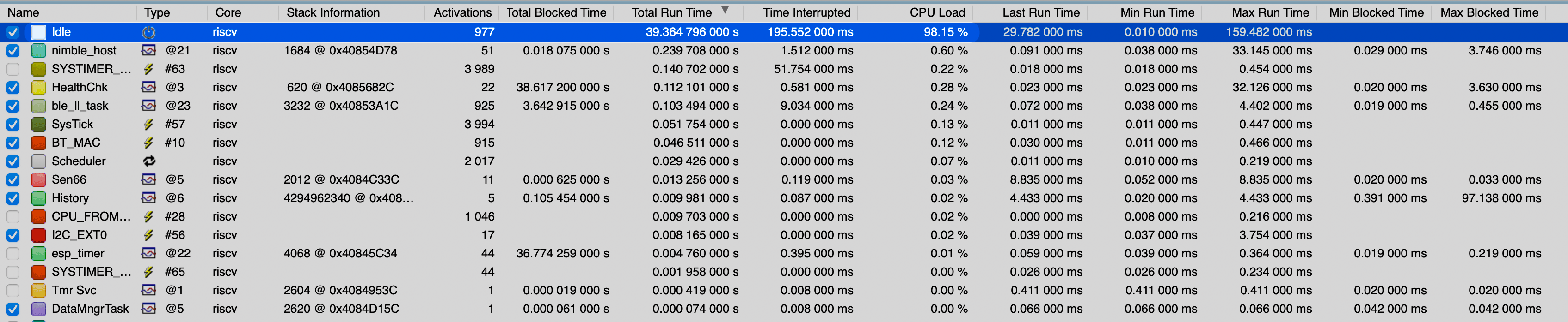
--rtos-debug flag.sh run.sh openocd.echo "esp sysview start file://airy.svdat" | nc localhost 4444echo "esp sysview stop" | nc localhost 4444airy.svdat into the SystemView application.Here is an example RTOS trace analysis:
From the Total Runtime view, the device spends most of its time in the Idle task. All application tasks account for less than 1% of the total runtime, which suggests the system has plenty of CPU headroom.
The trace also shows multiple additional tasks created by the tracing/debug tooling (goes beyond this screenshot) likely because the RTOS debug configuration changes task behavior and disables certain optimizations. For this analysis, that overhead is acceptable.
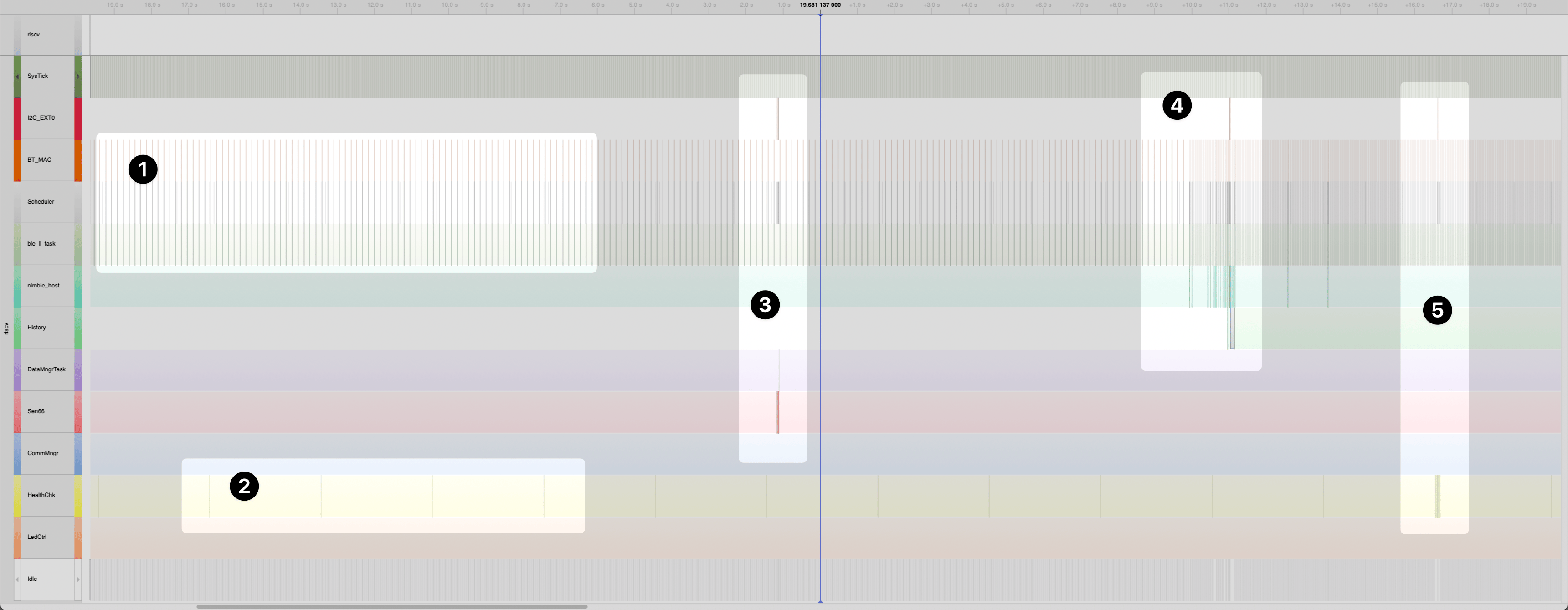
The next graph shows an RTOS timeline with a selected subset of tasks, making it easier to observe system behavior over time. The numbered markers highlight the following events:
airy/
├── src/                     # ESP-IDF firmware (C, + one C++ file)
│   ├── app_main.c           # Entry point / boot sequence
│   ├── tasks.{c,h}          # Central task stack sizes & priorities
│   ├── i2c.{c,h}            # Shared I2C master + bus mutex
│   ├── sen66.{c,h}          # SEN66 sensor driver & sampling task
│   ├── eeprom.{c,h}         # 24AA64 circular history log
│   ├── rtc.{c,h}            # PCF8523 + software-clock fallback
│   ├── button.{c,h}         # Multi-click gesture detection
│   ├── led.{c,h}            # LED status patterns
│   ├── crc.{c,h}            # Sensirion CRC-8 + CRC-16
│   ├── data_mngr.{c,h}      # Averaging, buffering, dispatch
│   ├── comm_mngr.{c,h}      # BLE/Matter selection & routing
│   ├── history.{c,h}        # EEPROM -> BLE history transfer task
│   ├── fault.{c,h}          # Fault log, severity, restart policy
│   ├── health_check.{c,h}   # Watchdog + periodic diagnostics
│   ├── device_cmd.{c,h}     # Maintenance command handlers
│   ├── ble_*.{c,h}          # NimBLE setup, adv, GAP, GATT, interface
│   └── matter_interface.cpp # esp-matter integration
├── ios-app/Airy/            # SwiftUI companion app
│   ├── Models/              # BLE Packet, AQI, EPA breakpoints, errors
│   ├── Services/            # BLE handlers, repository, storage, state
│   ├── Views/               # Dashboard, gauge, charts, settings, setup
│ └── Utilities/ # Design system & themePrerequisites
~/Developer/esp/esp-idf (or edit the paths in run.sh).~/Developer/esp/esp-matter.Firmware
sh run.sh build --release     # optimized build
sh run.sh flash --release     # flash optimized build
The device boots into BLE mode by default. Double-click the button to switch to Matter mode (it will reboot). In Matter mode, commission it with your hub using the standard Espressif test credentials – Apple Home accepts developer-mode devices with a warning; Home Assistant needs "Test Net DCL" enabled in the Matter integration.
iOS app
Open ios-app/Airy.xcodeproj in Xcode, then build and run it on a physical device
(CoreBluetooth is unavailable in the simulator). Grant the Bluetooth permission,
tap to discover Airy devices, and the app will connect, sync history, and start
streaming.
The firmware in this repository is licensed under the Apache License 2.0. The SwiftUI app is licensed under the Mozilla Public License 2.0 (MPL-2.0).
You are free to use, modify, and distribute this software in personal, educational, or commercial products under the terms of the Apache 2.0 License.
If you use or distribute this code (or modified versions of it), you must:
Component datasheets (bundled in docs/spec/):
docs/specs/SEN6x_datasheet.pdfdocs/specs/PCF8523_datasheet.pdfdocs/specs/24xx64_eeprom_datasheet.pdfSpecifications:
Architecture diagrams (PlantUML sources in docs/arch/):
rtos-architecture.puml – tasks,
queues, mutex, button ISR path.ble-gatt.puml – services, characteristics,
packet layout.ble-history.puml – history download sequence.Frameworks and SDKs:
| Qty | Value | Footprint | References |
|---|---|---|---|
| 4 | M3 | MountingHole:MountingHole_3.2mm_M3_Pad_Via | MH1, MH2, MH3, MH4 |
| 3 | 2k2 | Resistor_SMD:R_0805_2012Metric | R1, R2, R3 |
| 3 | Fiducial | Fiducial:Fiducial_1mm_Mask2mm | FM1, FM2, FM3 |
| 1 | 100nF | Capacitor_SMD:C_0805_2012Metric | C1 |
| 1 | 24AA64/P | Package_DIP:DIP-8_W7.62mm | U2 |
| 1 | Conn_01x04 | Connector_PinHeader_2.54mm:PinHeader_1x04_P2.54mm_Vertical | J3 |
| 1 | Conn_01x05 | Connector_PinHeader_2.54mm:PinHeader_1x05_P2.54mm_Vertical | J4 |
| 1 | Conn_01x05 | 0_breakout_boards:Adafruit PCF8523 | J1 |
| 1 | Conn_01x06 | Connector_PinHeader_2.54mm:PinHeader_1x06_P2.54mm_Vertical | J2 |
| 1 | RED | LED_SMD:LED_0805_2012Metric | D1 |
| 1 | SW_Push | Button_Switch_THT:SW_PUSH_6mm | SW1 |
| 1 | XIAO-ESP32-C6-DIP | xiao-esp32-c6:XIAO-ESP32-C6-DIP | U1 |
It measures 49 × 67 mm and has 2 copper layers, 1.6 mm thick.
19 parts, built around the 24AA64/P, CC0805KRX7R9BB104 and NCD0805R1. The full list of its parts is on this page, with links to each part's symbol and footprint where PCBKit's library has them.
From the iharhl/airy repository on GitHub, at the commit this page was made from: the board is pcb/pcb.kicad_pcb and its schematic pcb/pcb.kicad_sch. PCBKit opens the board in the browser, with nothing to install.
Its repository publishes it under the Apache-2.0 licence: you may reuse it on that licence's terms (keep the author's notice, and for a copyleft licence share your changes alike).
v-cu/dpf-load-monitor-wide
ESP32-P4 diagnostic display for VAG diesels — live DPF and engine data over CAN (UDS) on a 3.19" ultra-wide AMOLED. Firmware, KiCad files, BOM and 3D enclosure.

apuder/TRS-IO
TRS-IO gives a TRS-80 Model 1/III online capabilities and provides access to a variety of services. TRS-IO currently features the following capabilities:

lolz0r/Williams-WPC-Power-Driver-Board-A-12697-3
Untested, unverifed, AI created design.

Simplycissmus/windowmaster-s3-controller
Open hardware and ESP32-S3 firmware for a local 24 V window actuator controller with MQTT and Home Assistant integration.

gallicchio/motor-pid
The motor-position feedback loop of Learning the Art of Electronics (Hayes & Horowitz), Lab 10L, as a 170 x 120 mm printed circuit board whose silkscreen is the schematic.

Gamecard/k2-plus-cm5
K2 Plus CM5 – Creality K2 Plus mit Upstream-Klipper auf einem Raspberry Pi CM5

