
2 layers78 × 124 mm
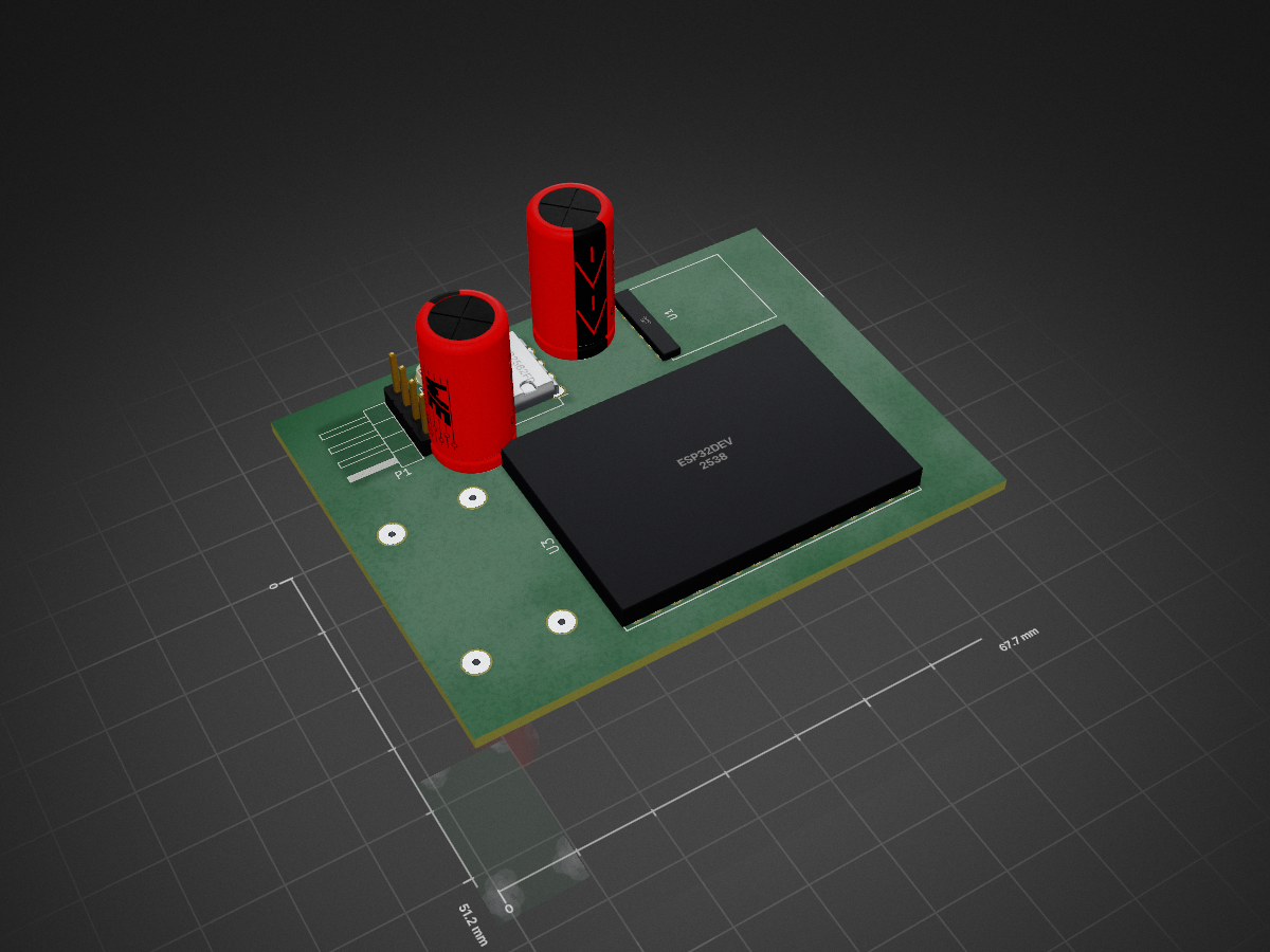
 ieb/WindSensorBase
RF -> NMEA2000 bridge used in conjunction with the WindSensor device. Coverts 2.4GHz rf output to NMEA2000 wind sentences at upto 5Hz.
WindSensorBase is an open-source printed circuit board by ieb, from the ieb/WindSensorBase repository on GitHub. It is a 2-layer board with 8 parts on 11 nets, routed with 114 tracks and 2 vias.
It is built around the MCP2562FD-E/P. Its parts include 4 ICs, 2 capacitors, 1 resistor and 1 connector. It belongs with the radio and wireless boards and the ESP32 boards of this library.
Reads data transmitted on 2.4GHz RF from a windsensor device and converts it into NMEA2000 Wind sentences for use on a NMEA2000 bus. The RF uses JDY-40 modules https://www.electrodragon.com/w/images/0/05/EY-40_English_manual.pdf based on a BEKEN RF Chip https://www.mikrocontroller.net/attachment/381910/BT-WiFi-52rf5541.pdf. Which claims a range of upto 120M (tested through walls and metal roofing at 40M no problems). The Base uses a ESP32 module (WROOM) with Wifi and BT disabled consuming about 80mA at 5V. CAN transcevers are MCP2562FD chips using 3.3V logic levels and 5V CAN driver voltage which seems to be compatible with most marine equipment expecting CANH at arround 4.5v.
The same setup could be used for any other RF Serial -> CANBus sensor, and the JDY-40 can switch RF channels relatively quickly, however for this application probably not fast enough to bridge Wind Readings at 10Hz. Reading data at 9600 1 line every 0.1s on a fixed RF channel works no problem as the underlying RF transport runs at 2Mb/s, but the JDY-40 wont switch reliably between channels using AT commands, see the doc on the ED-40 manual.
[ ] Implement CLI with configuration settings. [ ] Test on NMEA2000 bus
| Qty | Value | Footprint | References |
|---|---|---|---|
| 2 | 100nF | Capacitors_ThroughHole:C_Disc_D6_P5 | C1, C2 |
| 1 | 120R | Resistors_ThroughHole:Resistor_Horizontal_RM7mm | R1 |
| 1 | CONN_4 | Pin_Headers:Pin_Header_Angled_1x04_Pitch2.54mm | P1 |
| 1 | DCDCConverter | Divers:DC-DC-Converter | U2 |
| 1 | ESP32Dev | Housings_DIP:DIP-30_1_ELL | U3 |
| 1 | JDY40 | Divers:JDY-40-TH | U1 |
| 1 | MCP2562FD | Housings_DIP:DIP-8_W7.62mm_LongPads | IC1 |
8 parts, built around the MCP2562FD-E/P. The full list of its parts is on this page, with links to each part's symbol and footprint where PCBKit's library has them.
From the ieb/WindSensorBase repository on GitHub, at the commit this page was made from: the board is pcb/WindSensorBase.kicad_pcb. PCBKit opens the board in the browser, with nothing to install.
Its repository states no licence, so its author keeps all rights: ask ieb before reusing the design.

rbtsco/USB2CAN
Tiny USB to 8Mbps Flexible-Data CAN (/ AUVCAN) adapter based on the STM32L5 and MCP2562FD

bocabob/LCC-RPi-Pico-Board
KiCad files for a board supporting LCC CAN hardware implementation for RPiPico


AdrianR3/Clampinator
Inspired by the ODrive Regen Clamp, the clampinator is a custom built regeneration clamp targeting 16-60V systems.

ale-giustina/CAN-serializer
A 3 interface FDCAN serializer based on a STM32G473CCTx