6 layers130 × 112.6 mm
 AdrianR3/Clampinator
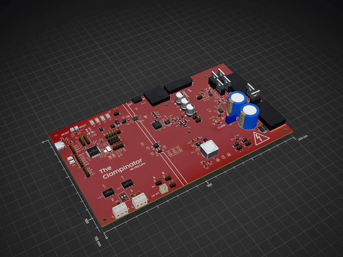
Inspired by the ODrive Regen Clamp, the clampinator is a custom built regeneration clamp targeting 16-60V systems.
Clampinator is an open-source printed circuit board by AdrianR3, from the AdrianR3/Clampinator repository on GitHub. It is a 4-layer board of 200 × 115 mm with 211 parts on 143 nets, routed with 1,350 tracks and 415 vias.
It is built around the MCP2562FD-E/P, TK100E10N1,S1X and PTS810SJM250SMTRLFS, with the SK6812MINI-E, SS34 and 100SXV15M among its other parts. Its parts include 59 capacitors, 42 resistors, 15 connectors, 11 diodes and 7 transistors.


Inspired by the ODrive Regen Clamp, the clampinator is a custom built regeneration clamp targeting 16-60V systems.
[!CAUTION] The Clampinator must not be plugged in unless the power switch is off. To turn on, slide power switch to
PRECHARGE, and only proceed toRUNafter allowing at least 1s for the bulk capacitors to charge.
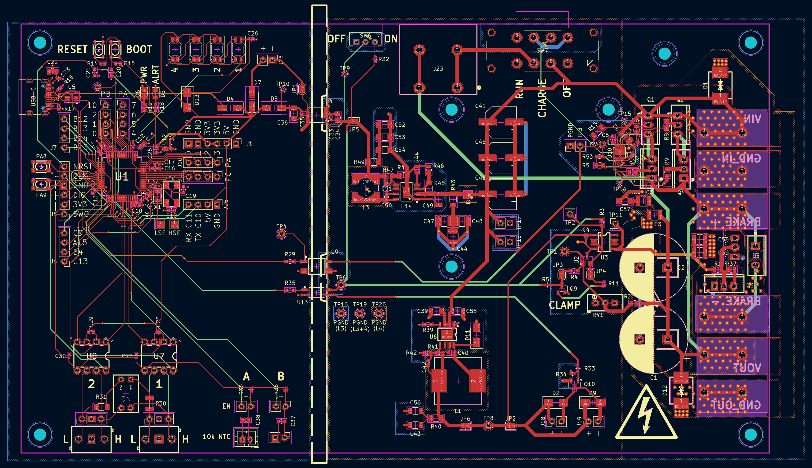
The STM32 on the board is equipped with two built in CAN FD controllers, and the Clampinator has two accompanying CAN transcievers in the bottom left of the board. There is dip switch SW5 which can be used to toggle the internal 120Ω termination resistors.
The Clampinator can be ordered from sites like JLCPCB. The KiCAD source files are in ./KiCAD and the production gerber files are in ./KiCAD/prod along with the bom.
| Qty | Value | Footprint | References |
|---|---|---|---|
| 13 | 100nF | Capacitor_SMD:C_0402_1005Metric | C4, C8, C12, C13, C14, C15, C17, C23, C26, C27, C28, C29, C30 |
| 8 | MountingHole | MountingHole:MountingHole_3.2mm_M3 | H1, H2, H3, H4, H5, H6, H7, H8 |
| 7 | 10k | Resistor_SMD:R_0402_1005Metric | R14, R15, R32, R34, R36, R38, R51 |
| 6 | Conn_01x04 | Connector_PinHeader_2.54mm:PinHeader_1x04_P2.54mm_Vertical | J6, J7, J8, J9, J10, J11 |
| 6 | TK100E10N1,S1X | easyeda2kicad:TO-220-3_L10.0-W4.5-P2.54-L | Q1, Q2, Q3, Q4, Q5, Q6 |
| 5 | 10R | Resistor_SMD:R_0805_2012Metric | R1, R6, R7, R8, R9 |
| 4 | 100nF | Capacitor_SMD:C_0603_1608Metric | C20, C21, C37, C38 |
| 4 | PTS810SJM250SMTRLFS | easyeda2kicad:KEY-SMD_4P-L4.2-W3.2-P2.20-LS4.6 | SW1, SW2, SW3, SW4 |
| 4 | SK6812MINI-E | LED_SMD:LED_SK6812MINI-E_3.2x2.8mm_P1.5mm | D10, D14, D15, D16 |
| 4 | SS34 | Diode_SMD:D_SMA | D4, D7, D8, D13 |
| 3 | 15uF 40mR | easyeda2kicad:CAP-SMD_BD8.0-L8.3-W8.3-LS9.3-FD | C41, C45, C46 |
| 3 | 2u2F | Capacitor_SMD:C_0603_1608Metric | C9, C10, C25 |
| 3 | 2u2F 9mR | Capacitor_SMD:C_1206_3216Metric | C52, C53, C54 |
| 3 | 4u7F | Capacitor_SMD:C_1210_3225Metric | C3, C58, C59 |
| 3 | 4u7F 1m73R | Capacitor_SMD:C_1210_3225Metric | C44, C47, C48 |
| 3 | PGND | TestPoint:TestPoint_THTPad_D2.0mm_Drill1.0mm | TP16, TP19, TP20 |
| 2 | 100k | Resistor_SMD:R_1206_3216Metric | R13, R45 |
| 2 | 100pF | Capacitor_SMD:C_0402_1005Metric | C42, C51 |
| 2 | 10pF | Capacitor_SMD:C_0402_1005Metric | C31, C32 |
| 2 | 10uF | Capacitor_SMD:C_0805_2012Metric | C22, C34 |
| 2 | 120R | Resistor_SMD:R_1206_3216Metric | R30, R31 |
| 2 | 120k | Resistor_SMD:R_0603_1608Metric | R39, R53 |
| 2 | 15nF | Capacitor_SMD:C_0402_1005Metric | C33, C35 |
| 2 | 1mF | Capacitor_THT:CP_Radial_D18.0mm_P7.50mm | C1, C2 |
| 2 | 22uF 3m298R | Capacitor_SMD:C_1206_3216Metric | C43, C56 |
| 2 | 2n2F 1R078 | Capacitor_SMD:C_0603_1608Metric | C40, C50 |
| 2 | 2u2F 1m73R | Capacitor_SMD:C_1206_3216Metric | C39, C55 |
| 2 | 30pF | Capacitor_SMD:C_0603_1608Metric | C18, C19 |
| 2 | 5k1 | Resistor_SMD:R_0402_1005Metric | R16, R17 |
| 2 | FAN | Connector_PinHeader_2.54mm:PinHeader_1x02_P2.54mm_Vertical | J18, J19 |
| 2 | MCP2562FD-E/P | easyeda2kicad:PDIP-8_L9.3-W6.4-P2.54-LS7.6-BL | U7, U8 |
| 2 | SS210 | Diode_SMD:D_SMA | D2, D9 |
| 2 | Screw_Terminal_01x03 | easyeda2kicad:CONN-TH_3P-P3.50_OSTTE030161 | J27, J28 |
| 2 | SolderJumper_2_Bridged | Jumper:SolderJumper-2_P1.3mm_Bridged_RoundedPad1.0x1.5mm | JP3, JP4 |
| 2 | SolderJumper_2_Bridged | Jumper:SolderJumper-2_P1.3mm_Bridged2Bar_Pad1.0x1.5mm | JP2, JP5 |
| 2 | VP0365840000G | imports:VP0265840000G_THT | J20, J24 |
| 1 | +15V R | TestPoint:TestPoint_THTPad_D2.0mm_Drill1.0mm | TP8 |
| 1 | +15VR | Jumper:SolderJumper-2_P1.3mm_Bridged2Bar_Pad1.0x1.5mm | JP6 |
| 1 | +5V INJ | Connector_PinHeader_2.54mm:PinHeader_1x02_P2.54mm_Vertical | J25 |
| 1 | +5VLR | TestPoint:TestPoint_THTPad_D1.0mm_Drill0.5mm | TP10 |
| 1 | +5VR | TestPoint:TestPoint_THTPad_D2.0mm_Drill1.0mm | TP6 |
| 1 | 100R | Resistor_SMD:R_0402_1005Metric | R33 |
| 1 | 100R | Resistor_SMD:R_0603_1608Metric | R18 |
| 1 | 100mR | Resistor_SMD:R_1206_3216Metric | R49 |
| 1 | 101k | Resistor_SMD:R_0805_2012Metric | R48 |
| 1 | 10k | Resistor_SMD:R_0805_2012Metric | R37 |
| 1 | 10k NTC | Connector_PinHeader_2.54mm:PinHeader_1x02_P2.54mm_Vertical | J15 |
| 1 | 10k NTC | Connector_JST:JST_PH_B2B-PH-K_1x02_P2.00mm_Vertical | J14 |
| 1 | 12k4 | Resistor_SMD:R_0402_1005Metric | R10 |
| 1 | 150 nH 85mR | pretty_imports:WE-MAPI_2010 | L2 |
| 1 | 180mR | Resistor_SMD:R_1206_3216Metric | R40 |
| 1 | 1R65 | Resistor_SMD:R_1206_3216Metric | R43 |
| 1 | 1uF | Capacitor_SMD:C_0402_1005Metric | C24 |
| 1 | 1uF | Capacitor_SMD:C_0603_1608Metric | C16 |
| 1 | 1uF | Capacitor_SMD:C_1206_3216Metric | C6 |
| 1 | 200k | easyeda2kicad:RES-ADJ-TH_3P-L9.5-W4.9-P2.50-L_3296W | RV1 |
| 1 | 20k | Resistor_SMD:R_0603_1608Metric | R44 |
| 1 | 220R | Resistor_SMD:R_0603_1608Metric | R19 |
| 1 | 22uF | Capacitor_SMD:C_1206_3216Metric | C36 |
| 1 | 2R2 | Resistor_SMD:R_1210_3225Metric | R50 |
| 1 | 2n2F 100V | Capacitor_SMD:C_0603_1608Metric | C7 |
| 1 | 2u2F | Capacitor_SMD:C_1206_3216Metric | C49 |
| 1 | 316k | Resistor_SMD:R_0603_1608Metric | R47 |
| 1 | 33uH 130mR | pretty_imports:IND_SRR6038-330Y | L3 |
| 1 | 34k | Resistor_SMD:R_0805_2012Metric | R46 |
| 1 | 470R | Resistor_SMD:R_0603_1608Metric | R3 |
| 1 | 470k | Resistor_SMD:R_0805_2012Metric | R5 |
| 1 | 470nF 50V | Capacitor_SMD:C_0603_1608Metric | C5 |
| 1 | 49k9 | Resistor_SMD:R_0603_1608Metric | R42 |
| 1 | 4k7 | Resistor_SMD:R_0402_1005Metric | R11 |
| 1 | 4n7F 100V | Capacitor_SMD:C_1206_3216Metric | C57 |
| 1 | 4u7F | Capacitor_SMD:C_0603_1608Metric | C11 |
| 1 | 510k | Resistor_SMD:R_0603_1608Metric | R4 |
| 1 | 560R | Resistor_SMD:R_0603_1608Metric | R35 |
| 1 | 576k | Resistor_SMD:R_0603_1608Metric | R41 |
| 1 | 680R | Resistor_SMD:R_0603_1608Metric | R29 |
| 1 | 68uH 61mR | easyeda2kicad:IND-SMD_L12.5-W12.5 | L1 |
| 1 | 82k | Resistor_SMD:R_0805_2012Metric | R2 |
| 1 | 850mV 5A | Diode_SMD:D_SMA | D11 |
| 1 | AO3400A | Package_TO_SOT_SMD:SOT-23 | Q10 |
The 163 most common of 211 parts.
It measures 200 × 115 mm and has 4 copper layers, 1.67 mm thick.
211 parts, built around the MCP2562FD-E/P, TK100E10N1,S1X, PTS810SJM250SMTRLFS and SK6812MINI-E. The full list of its parts is on this page, with links to each part's symbol and footprint where PCBKit's library has them.
From the AdrianR3/Clampinator repository on GitHub, at the commit this page was made from: the board is KiCAD/Clampinator.kicad_pcb and its schematic KiCAD/Clampinator.kicad_sch. PCBKit opens the board in the browser, with nothing to install.
Its repository states no licence, so its author keeps all rights: ask AdrianR3 before reusing the design.

Durant-li/smps-forward-converter
PLECS, MATLAB and KiCad design archive for a 30 Vac / 35 Vdc to 10 V isolated SMPS forward converter.

ParadigmEngineering/igvc-2023-hardware
Intelligent Ground Vehicle Competition (Spring 2023) hardware for the Paradigm Engineering Student Group

tudsat-rocket/stigma
core board and mission board for a new flight computer


Brunner-neutrino-lab/cremat-multi-channel-amplifier
12-channel SiPM CSP + shaper + BLR + buffer board, built from the reworked single channel (../../../integration/single-channel/design/) as the single source of truth.

irina-b-dev/custom_spad
; Assumes: ; - Pin 2 - 4,5 = pulse input ; - Pin 0 - 2,3 = gate/control pin ; - pin base in C must include both
