4 layers200 × 115 mm
Clampinator
AdrianR3/Clampinator
Inspired by the ODrive Regen Clamp, the clampinator is a custom built regeneration clamp targeting 16-60V systems.
211 parts

 irina-b-dev/custom_spad
; Assumes: ; - Pin 2 - 4,5 = pulse input ; - Pin 0 - 2,3 = gate/control pin ; - pin base in C must include both
Spad passive is an open-source printed circuit board by irina-b-dev, from the irina-b-dev/custom_spad repository on GitHub, published under the GPL-2.0 licence. It is a 2-layer board of 39 × 25.5 mm with 14 parts on 12 nets, routed with 33 tracks and 0 vias.
It is built around the LT1711IMS8#PBF, MTAPD-06-013 and CRT0402-BY-4992GLF, with the TNPW08051M00BEEN, 3296W-1-204LF and MKP1847510254K2 among its other parts. Its parts include 6 resistors, 4 connectors, 2 ICs and 1 capacitor.


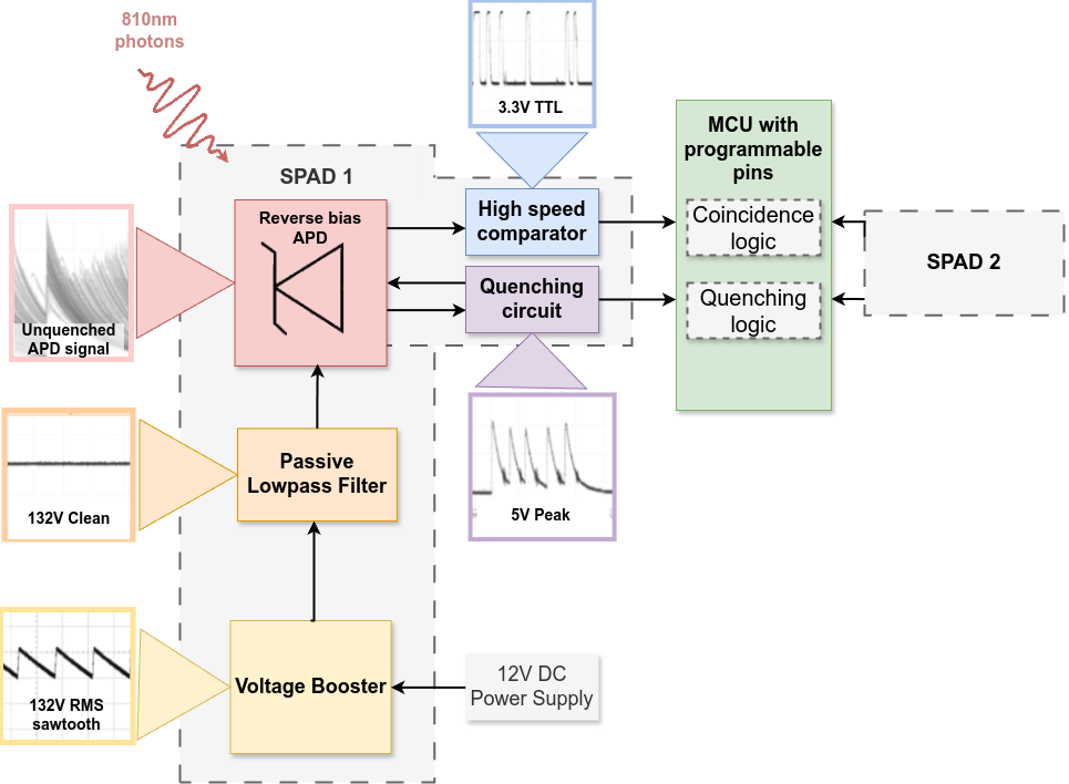
Minimal working
| Name | Link | Price | Qty | Description | Code | Check |
|---|---|---|---|---|---|---|
| APD | https://ro.mouser.com/ProductDetail/193-MTAPD-06-001 | 37,21 € | 2 | Peak Wavelength: 800nm | 193-MTAPD-06-001 | [x] |
| --- --- | ||||||||
| Ref. | Mfg. | Part No. | Description | |||||
| R | -- | -- | resistor | 100K | ||||
| C3 | -- | -- | capacitor | 1µF | ||||
| YH11068A | booster |
| --- --- | For SPAD | |||||||
| Ref. | Mfg. | Part No. | Description | |||||
| APD | -- | DAPD | diode | |||||
| C1 | -- | -- | capacitor | 33µF | 2.7V | |||
| C2 | -- | -- | capacitor | 1µF | ||||
| C3 | -- | -- | capacitor | 1µF | ||||
| C4 | -- | -- | capacitor | 1µF | ||||
| C5 | -- | -- | capacitor | 100nF | ||||
| C6 | -- | -- | capacitor | 10nF | ||||
| C7 | -- | -- | capacitor | 100nF | ||||
| C8 | -- | -- | capacitor | 100nF | ||||
| Cj | -- | -- | capacitor | 1pF | 1KV | |||
| Cn | -- | -- | capacitor | 10nF | ||||
| D1 | OnSemi | 1N5818 | diode | |||||
| D2 | OnSemi | 1N5819 | diode | |||||
| D3 | Vishay | BAT54 | diode | |||||
| D4 | Rohm | BAS21HY | diode | |||||
| D5 | Rohm | BAS21HY | diode | |||||
| L1 | -- | -- | inductor | 33µH | 1.35A pk | |||
| M1 | International Rectifier | IRF7832 | MOSFET | |||||
| M2 | Siliconix | Si7336ADP | MOSFET | |||||
| maboi | -- | -- | resistor | 1M | ||||
| R1 | -- | -- | resistor | 1M | 1.00% | 0.1W | ||
| R2 | -- | -- | resistor | 100K | ||||
| R3 | -- | -- | resistor | 49.9K | ||||
| R4 | -- | -- | resistor | 6.8K | ||||
| R5 | -- | -- | resistor | 20K | ||||
| R6 | -- | -- | resistor | 300 | ||||
| R7 | -- | -- | resistor | 1K | ||||
| R8 | -- | -- | resistor | 1.9K | ||||
| R9 | -- | -- | resistor | 6K | ||||
| R10 | -- | -- | resistor | 500K | ||||
| R11 | -- | -- | resistor | 1K | ||||
| R13 | -- | -- | resistor | 150K | ||||
| Rbias | -- | -- | resistor | 14K | ||||
| Rbias1 | -- | -- | resistor | 10K | ||||
| Rdivider | -- | -- | resistor | 140K | ||||
| Rdrain | -- | -- | resistor | 90K | ||||
| Re0 | -- | -- | resistor | 10 | ||||
| Ri | -- | -- | resistor | 200K | ||||
| Rth | -- | -- | resistor | 1M | ||||
| U1 | Analog Devices | LT1172 | integrated circuit | |||||
| U2 | Analog Devices | LT1711 | integrated circuit | |||||
| U3 | Analog Devices | AD8605 | integrated circuit | |||||
| RP_Pico | Rasberry Pi Pico | MCU | ||||||
.program detect_pulse

; Assumes:
; - Pin 2 - 4,5 = pulse input
; - Pin  0 - 2,3 = gate/control pin
; - pin base in C must include both

start:
    wait 1 pin 2           ; Wait for rising edge on pulse input
    ;wait 1 pin 0
    jmp pin do_push                       ;jmp pin do_push     ;
    jmp do_push     ;jmp start              ; Otherwise, skip

do_push:
    in x, 32               ;
    push block
jmp startThis project is part of a bigger project
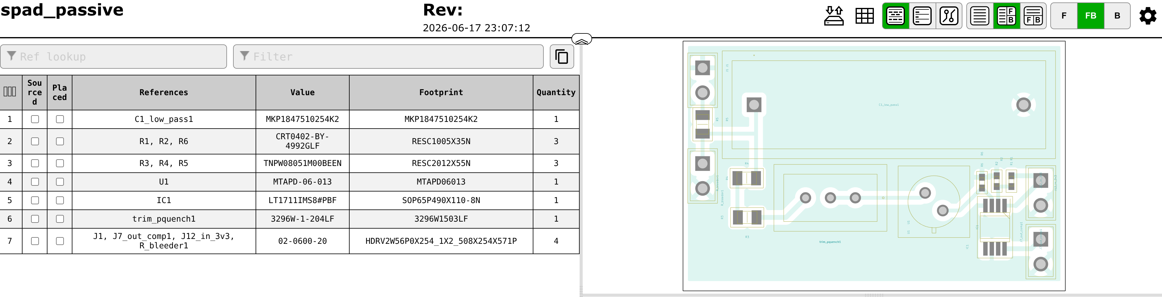
| Qty | Value | Footprint | References |
|---|---|---|---|
| 4 | 02-0600-20 | MyMegaLib:HDRV2W56P0X254_1X2_508X254X571P | J1, J7_out_comp1, J12_in_3v3, R_bleeder1 |
| 3 | CRT0402-BY-4992GLF | MyMegaLib:RESC1005X35N | R1, R2, R6 |
| 3 | TNPW08051M00BEEN | MyMegaLib:RESC2012X55N | R3, R4, R5 |
| 1 | 3296W-1-204LF | MyMegaLib:3296W1503LF | trim_pquench1 |
| 1 | LT1711IMS8#PBF | MyMegaLib:SOP65P490X110-8N | IC1 |
| 1 | MKP1847510254K2 | MyMegaLib:MKP1847510254K2 | C1_low_pass1 |
| 1 | MTAPD-06-013 | MyMegaLib:MTAPD06013 | U1 |
It measures 39 × 25.5 mm and has 2 copper layers, 1.6 mm thick.
14 parts, built around the LT1711IMS8#PBF, MTAPD-06-013, CRT0402-BY-4992GLF and TNPW08051M00BEEN. The full list of its parts is on this page, with links to each part's symbol and footprint where PCBKit's library has them.
From the irina-b-dev/custom_spad repository on GitHub, at the commit this page was made from: the board is kicad/spad_passive.kicad_pcb and its schematic kicad/spad_passive.kicad_sch. PCBKit opens the board in the browser, with nothing to install.
Its repository publishes it under the GPL-2.0 licence: you may reuse it on that licence's terms (keep the author's notice, and for a copyleft licence share your changes alike).
AdrianR3/Clampinator
Inspired by the ODrive Regen Clamp, the clampinator is a custom built regeneration clamp targeting 16-60V systems.

Brunner-neutrino-lab/cremat-multi-channel-amplifier
12-channel SiPM CSP + shaper + BLR + buffer board, built from the reworked single channel (../../../integration/single-channel/design/) as the single source of truth.


google/mozc-devices
Circuit diagrams and firmware source code for Gboard DIY keyboards


hackclub/OnBoard
💡 Join 1,000 teenagers and make your first PCB with a $100 grant!

