2 layers105 × 90 mm
Low Power Desktop Weather Station
jobitjoseph/Desktop-Weather-Station
This project offers a practical way to build a clean and minimal weather station using an ESP32 microcontroller and an E-Ink display.
65 parts4
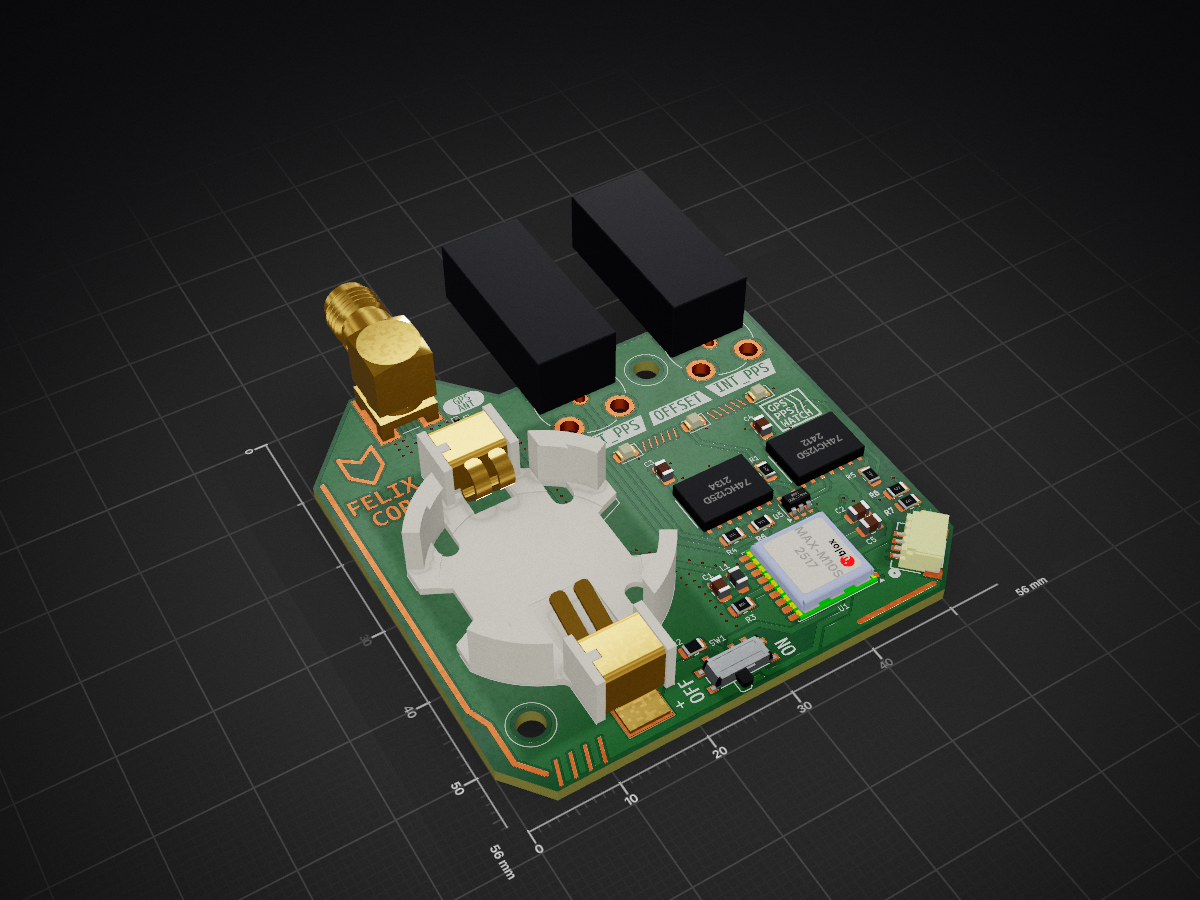
 idlehandsdev/pps-watch42
An extremely accurate watch that doesn't tell time.
Pps watch is an open-source printed circuit board by idlehandsdev, from the idlehandsdev/pps-watch repository on GitHub, published under the AGPL-3.0 licence. It is a 2-layer board of 56 × 56 mm with 39 parts on 32 nets, routed with 196 tracks and 118 vias.
It is built around the 74HC125D, 74AHC1G86SE and MAX-M10S, with the BU2450SM-JJ-GTR, CONSMA002-SMD-G-T and PESD0402-140 among its other parts. Its parts include 8 resistors, 5 capacitors, 4 ICs, 4 diodes and 4 connectors. It belongs with the wearables boards of this library.


See the schematic for full signal flow and the BOM for part numbers.
This is a KiCad project. PCB mechanical design and 3D assembly were done in Fusion 360.
Fusion 360 share link: https://a360.co/4xXmWnG
| Reference | Qty | Value | Digikey Part No. |
|---|---|---|---|
| AE3 | 1 | YEGT002AA | 2958-YEGT002AA-ND |
| BT2 | 1 | BU2450SM-JJ-G | BU2450SM-JJ-GCT-ND |
| C1 | 1 | 100pF C0G | 311-1111-1-ND |
| C2, C3, C4, C5 | 4 | 0.1uF | 311-4348-1-ND |
| D1 | 1 | LED Red 0805 | 160-1415-1-ND |
| D2 | 1 | PESD0402-140 | PESD0402-140CT-ND |
| D3, D4 | 2 | LED Green 0805 | 475-LGR971-KN-1TR-ND |
| J1, J4 | 2 | BNC 2466267-1 | 17-2466267-1-ND |
| J2 | 1 | CONSMA002-SMD-G-T | 343-CONSMA002-SMD-G-TCT-ND |
| J6 | 1 | Qwiic | 1568-14417-ND |
| L1 | 1 | Ferrite Bead | 490-1040-1-ND |
| R1 | 1 | 470R | 311-470ARCT-ND |
| R2 | 1 | 500mA PolyFuse | F2772CT-ND |
| R3, R6 | 2 | 10K | 311-10KARCT-ND |
| R4, R5 | 2 | 330R | 311-330ARCT-ND |
| SW1 | 1 | Power Switch SPDT | 401-2016-1-ND |
| U1 | 1 | MAX-M10S | 672-MAX-M10S-00BTR-ND |
| U3, U6 | 2 | 74HC125D | 74HC125DCT-ND |
| U5 | 1 | 74AHC1G86 | 296-1094-1-ND |
Print the following files from the CAD/ folder:
CAD/pcb_frame_mount.stl -- frame that holds the PCBCAD/watch_band_mount.stl -- mounts the band to the frameAny standard 22mm watch band works. Tested with:
Bandini Nylon Sports Watch Band Strap 22mm
Felix Corp -- Idle Hands Dev R&D Division Asset Tag: FC-IDH-UTC-001
| Qty | Value | Footprint | References |
|---|---|---|---|
| 4 | 0.1uF | Capacitor_SMD:C_0805_2012Metric | C2, C3, C4, C5 |
| 3 | 330R | Resistor_SMD:R_0805_2012Metric | R1, R4, R5 |
| 2 | 10K | Resistor_SMD:R_0805_2012Metric | R3, R6 |
| 2 | 2466267-1 | project_footprints:TE_2466267-1 | J1, J4 |
| 2 | 4.7K | Resistor_SMD:R_0805_2012Metric | R7, R8 |
| 2 | 74HC125D | project_footprints:SOIC14_TOS | U3, U6 |
| 2 | LED_G | LED_SMD:LED_0805_2012Metric | D3, D4 |
| 1 | 0R | Resistor_SMD:R_0805_2012Metric | R2 |
| 1 | 100pF C0G | Capacitor_SMD:C_0805_2012Metric | C1 |
| 1 | 74AHC1G86 | Package_TO_SOT_SMD:SOT-23-5 | U5 |
| 1 | BU2450SM-JJ-G | project_footprints:BAT_BU2450SM-JJ-G | BT2 |
| 1 | CONSMA002-SMD-G-T | project_footprints:LINX_CONSMA002-SMD-G-T | J2 |
| 1 | G*** | kibuzzard-6A2251CD | kibuzzard-6A2251CD |
| 1 | G*** | kibuzzard-6A225147 | kibuzzard-6A225147 |
| 1 | G*** | kibuzzard-6A225392 | kibuzzard-6A225392 |
| 1 | G*** | kibuzzard-6A226675 | kibuzzard-6A226675 |
| 1 | G*** | kibuzzard-6A2255A9 | kibuzzard-6A2255A9 |
| 1 | G*** | kibuzzard-6A225EFE | kibuzzard-6A225EFE |
| 1 | G*** | kibuzzard-6A22543C | kibuzzard-6A22543C |
| 1 | G*** | kibuzzard-6A2254F6 | kibuzzard-6A2254F6 |
| 1 | G*** | kibuzzard-6A225388 | kibuzzard-6A225388 |
| 1 | G*** | kibuzzard-6A2263B9 | kibuzzard-6A2263B9 |
| 1 | G*** | kibuzzard-6A226669 | kibuzzard-6A226669 |
| 1 | LED_RED | LED_SMD:LED_0805_2012Metric | D1 |
| 1 | L_Ferrite | Inductor_SMD:L_0805_2012Metric | L1 |
| 1 | MAX-M10S | RF_GPS:ublox_MAX | U1 |
| 1 | PESD0402-140 | Diode_SMD:D_SOD-923 | D2 |
| 1 | QWIIC | project_footprints:CONN_SM04B-SRSS-TB_JST | J6 |
| 1 | power_sw | Button_Switch_SMD:SW_SPDT_PCM12 | SW1 |
It measures 56 × 56 mm and has 2 copper layers, 1.6 mm thick.
39 parts, built around the 74HC125D, 74AHC1G86SE, MAX-M10S and BU2450SM-JJ-GTR. The full list of its parts is on this page, with links to each part's symbol and footprint where PCBKit's library has them.
From the idlehandsdev/pps-watch repository on GitHub, at the commit this page was made from: the board is kicad/pps_watch.kicad_pcb and its schematic kicad/pps_watch.kicad_sch. PCBKit opens the board in the browser, with nothing to install.
Its repository publishes it under the AGPL-3.0 licence: you may reuse it on that licence's terms (keep the author's notice, and for a copyleft licence share your changes alike).
jobitjoseph/Desktop-Weather-Station
This project offers a practical way to build a clean and minimal weather station using an ESP32 microcontroller and an E-Ink display.

adamjvr/fantoccia
An Open Source DAQ hardare system based on https://github.com/marionette-daq/marionette-hardware


gadjet/Window-Door-sensor-Version-5
Version 5 of the Window/Door sensor project this time with ultra low current consumption


anwaypimpalkar/smartElevatorSystem
A holistic device for safer and smarter contactless elevator system using Embedded Machine Learning on an Arduino Nano 33 BLE Sense, complete with a deployable PCB and fire safety system pipeline.